Tag Archives: Norman Quesnel

Industry Developments: Cooling Solar Power Inverters

By Norman Quesnel, Senior Member of Marketing Staff
Advanced Thermal Solutions, Inc.

(This article will be featured in an upcoming issue of Qpedia Thermal e-Magazine, an online publication dedicated to the thermal management of electronics. To get the current issue or to look through the archives, visit http://www.qats.com/Qpedia-Thermal-eMagazine.)

Traveling across the U.S. one will find the widening use of renewable energy systems, including large scale solar and wind farms. The power from these installations is clean, emission-free and relatively low cost. Their own energy sources are free and endless: the wind and the sun.

Wind energy has become a cost-effective power source, competing with installations of coal, gas and nuclear power. So too has solar power, which is the focus of this article.

Solar power is doing more than ever to help meet energy demands for local power and for feeding power back to the electric grid. Today’s U.S. solar installations exceed 3,100 megawatts, enough to power more than 630,000 homes. The price of solar panels has dropped by nearly a third since 2010 and costs continue to fall. Manufacturers in the U.S. are also exporting billions of dollars worth of solar products. [1]

Figure 1. Wind and Solar Power Installations Share Some Thermal Management Issues with Other Electronics Systems. [2]

Most thermal management issues in solar power systems occur with their inverter systems. Here, the solar-generated DC power is converted to AC for power grids or local use. While these inverter systems can be very efficient, some excess heat must be managed so it doesn’t affect the inverter’s life or performance.

Cooling Solar Energy Inverters

Some solar power systems produce steam to spin turbines and generate electricity. But the more common solar systems are photovoltaic (PV) solar power facilities. In these, solar panels absorb and convert sunlight into electricity with the use of inverters. One or more solar inverters, or PV inverters, converts the sun-sourced, variable DC output of the PV panels into alternating current, AC. This is then fed into a commercial electrical grid or used by a local, off-grid electrical network. AC is the standard used by all commercial appliances, which is why many view inverters as the gateway between the photovoltaic (PV) system and the energy off-taker. [3]

Inverters are standard in PV solar systems whether they’re kW range residential systems to MW sized power plants. Larger installations may use a central inverter or a series of string inverters.

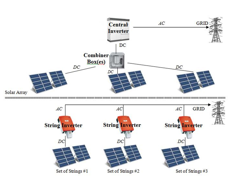
In a central inverter set up, the DC power from multiple solar panel arrays runs to combiner boxes and then to the inverter which converts it to AC. In a string inverter scheme, there are smaller, individual inverters for several panel arrays. The DC power runs directly into a string inverter rather than a combiner box and is converted to AC. While string inverters are used in residential to medium-sized commercial PV systems, central inverters are common to large commercial and utility-scale sites. [4]
Solar Power Inverters

Figure 2. Photovoltaic Solar Panel Installations Can Feature a Central Inverter or a Series of String Inverters. [4]

There are also solar microinverters that convert the DC generated by a single solar module to AC. The output from several microinverters is combined and often fed to the electrical grid. Microinverters are an alternative to conventional string and central solar inverters, which are connected to multiple solar modules or panels of the PV system. The main advantage of microinverters is that small amounts of shading, debris or snow on any one solar module, or even a complete module failure, do not disproportionately reduce the output of the entire array. [5]

Whatever its configuration, the PV inverter determines the amount of AC watts that can be distributed for use, e.g. to a power grid. For example, a PV system comprising 11 kilowatts DC (kWDC) worth of PV modules, connected to a 10-kilowatt AC (kWAC) inverter, will be limited to the inverter’s maximum output of 10 kW. [6]

There is also some power loss in the DC-AC conversion process. At the MW scale this could significantly impact a plant’s capacity (and revenue). But fortunately, inverter technologies have been advancing and expanding. The efficiency of state-of-the-art converters is more than 98 percent.

In addition to converting DC to AC, today’s inverters provide other services to help ensure their systems operate at optimal performance level. These include data monitoring, advanced utility controls, applications and system design engineering. Some inverters provide maximum power point tracking (to maximize power extraction), and anti-islanding protection (automatic shutdown). [7]

Cooling PV Solar Inverters

All inverters generate excess heat, especially utility-scale central inverters. Solar inverters used in the kW range are typically contained in finned metal housings that provide cooling via natural convection. Large-scale PV inverters are typically between 1 and 2 MW and the heat they generate directly correlates with their conversion efficiency. For an example, a 1 MW inverter with 98 percent conversion efficiency is generating about 20 kW of thermal energy. This is enough heat to comfortably warm 10 homes. [8]

Cooling solutions are typically needed inside inverters to protect their IGBT (insulated-gate bipolar transistors) modules. These solid state power semiconductor devices are electronic switches and consist of many devices in parallel. The design of the IGBTs and their cooling systems are among the most important aspects in protecting inverters and improving their conversion efficiency.

Improper IGBT design results in lower efficiency with higher heat exhaust. Cooling this heat requires a more complex and powerful cooling system. Better thermal management for the switching devices is essential to entering the next era of PV inverter efficiency, beyond 99 percent.

The recently-introduced PVS980 1500 VDC outdoor central inverter by ABB is optimized for large multi-megawatt solar power plants. The PVS980 features a self-contained cooling system to ensure outstanding endurance in tough environments with minimal maintenance. The cooling system uses phase transition and thermosiphon technology to prevent external air from entering the critical compartments of the inverter. This reduces the risk of corrosive gases or sand entering the inverter and causing damage. [9]

Solar Power Inverters

Figure 3. The Cooling System in ABB’s PVS980 Outdoor Central Inverter Uses Phase Transition and Thermosiphon Technology. [9]

The PVS980 inverter can operate from below freezing to extreme heat in 100 percent humidity without jeopardizing functionality. With the simplicity of air cooling and with the power density of a liquid cooled inverter, ABB’s inverter has very high total efficiency and low maintenance. There are no fillable liquids, pumps, valves, inhibitors and thus no leaks. All this makes the PVS980 suitable for any outdoor utility-scale PV plant.

Solar Power Inverters

Figure 4. The LV 5 Series Solar Inverter from GE Power Conversion Features a Liquid Cooling System. [10]

Some of the recent advancement in the inverter cooling system, such as an advanced hybrid cooling solution, requires significantly less air-flow in the system without an auxiliary fan power load. This lower load condition allows the inverter to further increase conversion efficiency. [11]

Solar Power Inverters

Figure 5. Outdoor Central Solar Inverter Whose Power Semiconductors, Inductor and Internal Ambient Air are Cooled by a Two-Phase System. [10]

Parker provides utility scale inverters with two-phase refrigerant cooling systems. The have a high efficiency design that integrates proven insulated gate bipolar transistor power conversion and magnetics with Parker cooling technology. No air conditioner is required. Power semiconductors, inductor, and internal ambient are all cooled by the integral two-phase system. Multiple access panels simplify installation and scheduled maintenance. [11]

The small footprint and high reliability of Parker’s outdoor central solar inverter is made possible by an advanced cooling system that uses a non-conductive, non-corrosive liquid to cool critical components. The refrigerant requires only 13 percent of the flow rate of an equivalent water/glycol based system. The cooling system runs efficiently by capitalizing on the tremendous amount of heat that is transferred as the refrigerant vaporizes, then releasing the heat through a condenser. No compressor is needed. Redundant system components allow inverter operation even after loss of a pump or a fan

Solar Power Inverters

Figure 6. IGBTs Mounted on a Cold Plate Inside a Central Solar Inverter. [11]

Compared to air cooling, with Parker’s solar inverter design IGBT temperatures are kept more constant over time. Advanced cooling is used on both the IGBT devices and the high efficiency inductors, as well as with a unique cool door feature that circulates temperature controlled air inside the sealed enclosure. Heat from the coolant loop is removed by an isolated heat exchanger, with no air exchange from the enclosure interior to the outside environment. Heat exchanger fans are variable speed for maximum efficiency. They are designed for redundancy and are monitored for rotation. In the event of a fan or coolant pump malfunction, the inverter will continue to operate, folding back power if necessary. The cooling system is designed for a minimum of maintenance, and there are no air filters to change.

Solar Power Inverters

Figure 7. Fan-less Heat Pipe Cooling is Used Up to 50% Load in This Toshiba 1500VDC PV Inverter. [12]

Another producer of large scale PV inverters is TMEIC (Toshiba Mitsubishi-Electric Industrial Systems Corporation). Their Samurai inverter series has power ratings up to 2700 kW. Each model has an advanced hybrid cooling system that uses heat pipe technology. The heat pipes allow the system to operate up to 50 percent load without turning on fans. The heat pipe cooling uses fewer parts and a slow speed fan. The fan-less mode runs when the inverter is below 50 percent load at 50°C. Natural convection provides the necessary cooling. Cool air enters from the bottom, flows through the heat pip, and hot air is exhausted from the top. [12]

Conclusion

A PV solar power system’s current inverter determines the amount of AC watts that can be distributed for use, e.g. to a power grid. For systems operating in the megawatt output range, the inverters will require some level of thermal management to cool their IGBT systems. Many of these large inverter systems have custom cooling solutions that can differ from each other (e.g. air cooling vs. liquid cooling) but all methods have their origins in cooling electronics other than those found in the solar power industry.

References
[1] http://www.cleanlineenergy.com/technology/wind-and-solar
[2] Photo by American Public Power Association on Unsplash
[3] http://www.solarpowerworldonline.com/2013/04/how-do-solar-inverters-work/
[4] http://cenergypower.com/blog/string-vs-central-inverters-choosing-right-inverter/
[5] https://en.wikipedia.org/wiki/Solar_micro-inverter
[6] http://www.solarmango.com/scp/solar-inverter-the-brain-of-a-solar-power-plant/
[7] https://en.wikipedia.org/wiki/Photovoltaic_system
[8] http://www.solarpowerworldonline.com/2015/02/new-age-solar-inverter-conversion-efficiency-99/
[9] http://www.abb.com/cawp/seitp202/db94b0aa1e8655a9c1257fdb0043680e.aspx
[10] http://www.gepowerconversion.com/sites/gepc/files/downloads/Solar_Single_Pages.pdf
[11] http://www.parker.com/literature/Renewable%20Energy/Parker_RenewablesBrochure__NA_7-2_spreads_lr.pdf
[12] https://www.tmeic.com/Repository/Others/Solar_Ware_Samurai_brochure_Rev-T-July2016.pdf

Industry Developments: Cooling Nuclear Power Plants

By Norman Quesnel, Senior Member of Marketing Staff
Advanced Thermal Solutions, Inc.

(This article will be featured in an upcoming issue of Qpedia Thermal e-Magazine, an online publication dedicated to the thermal management of electronics. To get the current issue or to look through the archives, visit http://www.qats.com/Qpedia-Thermal-eMagazine.)

Most man-made electricity in the U.S. is provided by thermoelectric power plants. In these large scale installations, water is boiled to steam to spin the plant’s turbines and to ultimately generate electricity. To provide the heat necessary to produce this steam, a power plant could burn coal, natural gas or oil. But, in fact, most plants don’t burn anything. Instead, they use a very hot, but carefully controlled core of nuclear material to provide the thermal energy for continuous steam.

Most large power plants use pressurized water reactors (PWRs) with nuclear fuel as their power source. There are different cooling requirements inside these plants and they are typically achieved with primary, secondary and tertiary thermal solutions. First, heat must be managed inside their reactor vessels where the radioactive material is housed. Then, in the steam generators, hot water from the reactor vessels is cooled by transferring its heat to a separated water source, converting it to steam. Lastly, after the steam moves past the turbines, it is condensed back to liquid water, which then returns to the steam generator. An illustration of a nuclear power plant with a pressurized water reactor is shown in Figure 1. [1]

Nuclear  Power Plant

Figure 1. Components of a Pressurized Water Reactor in a Nuclear Power Plant. [2]

Inside a PWR’s reactor core, the primary coolant, usually ordinary water, is heated by energy from atomic fission. Under high pressure to keep it from boiling, the heated water flows along a primary, closed-loop piping system into a steam generator. Here, the heat from the primary loop transfers into an isolated, lower-pressure secondary loop also containing water.

The water in the secondary loop enters the steam generator at a pressure and temperature slightly below that required to initiate boiling. Upon absorbing heat from the primary loop, it becomes saturated and slightly super-heated. The water changes phase to steam, which serves as the working fluid to push the turbine blades and generate electricity.

Finally, the steam is condensed back to water and re-enters the secondary loop. There are different ways to provide this tertiary level of cooling to cause this condensation. [3]

Fueling a Nuclear Reactor

A nuclear power plant’s reactor is most often fueled by U-235, a type of uranium that fissions easily. U-235 is a component of uranium hexafluoride fuel, which is made from mined or milled uranium oxide, called yellowcake. To make the uranium hexafluoride usable as a fuel, it is enriched to increase its U-235 content from 1 percent up to 3-5 percent. This is a low concentration and the enriched uranium is stable over a wide range of environmental conditions.

After the uranium hexafluoride is enriched, a fuel fabricator converts it into uranium dioxide powder and presses the powder into solid fuel pellets. The fabricator loads the ceramic pellets into long, pencil-thin rods made of a noncorrosive material, usually a zirconium alloy. These tubes, each about 4 meters long, are grouped by the hundreds into bundles that are called fuel assemblies. [4]

Figure 2. A Pressurized Water Reactor Includes Inlets and Outlets for Passing Water Coolant. [5]

A single fuel rod assembly for a pressurized water reactor (PWR) is approximately 13 feet high and weighs about 1,450 pounds. [6]

Step 1. Cooling the Nuclear Core

During a nuclear fission chain reaction, fuel rods heat up to about 800°C. If they are left uncovered by water, they’ll reach temperatures well about 1,000°C and begin to oxidize. That oxidation will react with any water that remains in the vicinity, producing highly explosive hydrogen gas. So, fuel rods are kept submerged in demineralized water, which serves as the primary coolant. The water is kept in a pressurized containment vessel and reaches about 325°C. [7]

At the atomic level, continuous exothermic fission in the fuel rods releases heat into the water in the PWC’s reactor. Nuclear power plants manage this fission and its resulting heat with the use of control rods. The rate of fission can be controlled–even stopped–by inserting and removing the control rods in the reactor. The control rods are made with neutron-absorbing material such as cadmium, hafnium or boron. Their presence controls the rate of nuclear reaction by absorbing neutrons, which otherwise would contribute to the fission chain reaction.

Figure 3. Control Rods Manage the Fission Rate Inside Nuclear Reactor Cores.

A single uranium fuel pellet the size of a fingertip contains as much energy as 17,000 cubic feet of natural gas or 1,780 pounds of coal. This relatively clean energy property, along with its vast half-life (700 million years), makes U-235 a viable alternative to burning fossil fuels to turn power plant turbines. [6]

Control Rod Drive Mechanisms (CRDMs) lower, raise, and keep in position assemblies of control rods inside a nuclear reactor. The rods absorb free neutrons, limiting the number available to cause fission of nuclear fuel. [8]

Step 2: Heat Transfer in Steam Generators

In a PWC-style nuclear power plant, the primary coolant, carrying heat from the reactor core, flows through a looped system into and out of a steam generator. Inside the generator it transfers its heat to an isolated, secondary coolant, water, converting it to steam. This steam travels in a secondary loop to the turbines. The transfer of heat from the primary loop to the secondary loop is accomplished without mixing the two fluids to prevent the secondary coolant from becoming radioactive.

Figure 4. Illustration of a Steam Generator. [9]

Figure 4. Illustration of a Steam Generator. [9]

There are multiple generators in a nuclear power plant. Each can measure up to 70 feet in height and weigh as much as 800 tons. A generator has more than 10,000 tubes, adding up to hundreds of miles in total length. A steam generator’s tubes are in a U-shape formation and each tube is about 19mm in diameter. Coolant from the reactor enters the generator’s inlet nozzle and circulates through the U-tubes.

The secondary coolant flows upward by natural convection through the bundle absorbing heat from the tubes of primary coolant. As heat is transferred through the tube walls, the secondary coolant, water, is turned into steam that flows from the top of the generator.

The materials that make up the steam generators and tubes are specially made and specifically designed to withstand heat, thermal expansion, high pressure, corrosion and radiation. The tubes are an important barrier between the radioactive and non-radioactive sides of the plant. For this reason, the integrity of the tubing is essential in minimizing the leakage of water between the two sides. [9]

Figure 5.  Steam Generator Tubes Transfer Heat from the Primary to the Secondary Loop. [8]

Figure 5. Steam Generator Tubes Transfer Heat from the Primary to the Secondary Loop. [8]

Step Three: Condensing the Steam

Once the steam has passed through a turbine, it must be cooled back into water by a third process and returned to the steam generator to be heated once.

Figure 6. Simple Illustration of Recirculation Scheme for Power Plant Steam. [10]

Figure 6. Simple Illustration of Recirculation Scheme for Power Plant Steam. [10]

There are three main methods of cooling a power plant’s steam and residual hot water:

Once-through systems take water from nearby sources (rivers, lakes, oceans), circulate it through condensers, and discharge the now warmer water to the local source. Once-through systems were initially popular because of their simplicity, low cost, and the abundant supplies of cooling water. But these systems can cause disruptions to local ecosystems, mainly from the large water withdrawals.

Wet recirculating systems reuse cooling water in a second cycle rather than immediately discharging it back to the original water source. Typically, wet recirculating systems use cooling towers to expose water to ambient air. Some water evaporates, but the rest is sent back to the condenser in the power plant. Because wet-recirculating systems only withdraw water to replace what’s lost through evaporation, these systems have much lower water withdrawals than once-through systems. Before being fed into the steam generator, the condensed steam (referred to as feed water) is sometimes preheated in order to minimize thermal shock.

More recently, plants have started using a third type of steam cooling system called dry cooling. Instead of using water to lower cooling water temperature, these systems use air passed over the cooling water by one or more large fans. Running those fans can require a significant amount of electricity, which makes this system less suited for large plants that require a lot of steam such as those powered by coal or nuclear energy. [11]

Three Integrated Cooling Systems

The illustration below is a simplified look at the main cooling loops in the Davis-Besse nuclear power station in Ohio. It features a pressurized water reactor in which uranium fuel is in long metal fuel rods (1) leading down to the reactor core (2). The reactor core is inside the reactor vessel (3) which is filled with purified water. Control rods (4) on top of the reactor start and stop the chain reaction that produces heat. When the rods are withdrawn, the nuclear chain reaction occurs, producing heat.

Figure 7. The Three Main Cooling Loops in a Nuclear Power Plant. [12]

Figure 7. The Three Main Cooling Loops in a Nuclear Power Plant. [12]

The water inside the Davis-Bessie PWR is under pressure so it won’t boil as its temperature rises by passing through the nuclear core. The water then travels along tubes through the steam generator (5) and back to the reactor. This constitutes the primary loop (green). After it has passed through the steam generator, the water has cooled down. The average temperature in this cycle is maintained at 582°F.

When the primary coolant water passes through the steam generator, its heat is transferred to the secondary loop (blue). Heat is transferred without the water in the primary loop and secondary loop ever coming in contact with each other. The water in the secondary loop boils to steam in the steam generator. This steam flows to the turbine generator (6). It is here that the steam’s energy is made into electricity.

When the steam leaves the turbine, it comes in contact with pipes carrying cooling water. As the steam cools, it changes back into water. The third loop (yellow) contains the water that is cooled by the large cooling tower (7). [12]

Among all of the power plants in the US, just over half reuse their cooling water. The rest are either dry systems or hybrid systems which can switch between dry and some sort of wet cooling depending on the temperature and availability of water.

References:
[1] Bright Hub Engineering, http://www.brighthubengineering.com/power-plants/2722-components-of-nuclear-power-plant-coolant/
[2, 3] http://www.world-nuclear.org/information-library/nuclear-fuel-cycle/nuclear-power-reactors/nuclear-power-reactors.aspx
[4] https://en.wikipedia.org/wiki/Nuclear_reactor_core
[5] https://commons.wikimedia.org/wiki/File:The_pressurized_water_reactor_of_NS_Savannah.jpg
[6] Nuclear Energy Institute, http://www.nei.org/Knowledge-Center/Nuclear-Fuel-Processes
[7] http://energy.gov/sites/prod/files/2014/01/f7/csp_review_meeting_042313_martin.pdf
[8] Vallourec, http://www.vallourec.com/NUCLEARPOWER/EN/products/nuclear-island/Pages/crdm.aspx
[9] http://cdn.intechopen.com/pdfs-wm/14150.pdf
[10] Union of Concerned Scientists, http://www.ucsusa.org/clean_energy/our-energy-choices/energy-and-water-use/water-energy-electricity-cooling-power-plant.html#.V8i9Cs9ATct
[11] https://en.wikipedia.org/wiki/Pressurized_water_reactor
[12] http://www.co.ottawa.oh.us/ottawacoema/davisbesse.html