Tag Archives: thermal design

Use High-Capacity Air Coolers in Place of Liquid Cooling for 200W+ Components

When server components reach 150W and higher TDP (total dissipated power), hardware engineers tend to look to cool them with liquid. These will provide effective thermal relief, if applied properly, but liquid cooling brings more concerns into the server chassis. These include pumps that can fail, seals that can leak, liquids that can foul, and a leap in the system TCO (total cost of ownership). But liquid cooling may not be needed at these power levels.

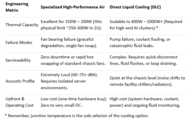
No matter what thermal management system you choose, the key criterion for component cooling is the internal junction temperature (Tj), short for junction temperature. This is the hottest temperature of a semiconductor device’s silicon die during operation. While there is correlation between junction temperature and power use, these vary by types of devices. Selection of a cooling system solely to power use is not necessarily going to manage the heat output from its junction temperature. However, for the sake of clarity and conveyance of cooling options, here we refer to power as the beacon for cooling option.

There is a range of high-capacity, non-liquid solutions available to effectively cool components running up to 200W. These cooler can even be deployed in tight headroom 1U and 2U chassis. They combine high density fins with high-output, high-power fans to cool components including AI processors, CPUs, FPGAs and GPUs.

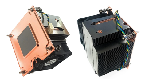
Figure 1 – A 2U Active Vapor Chamber 200W CPU Cooler with a Rated Speed of PWM 2600-8000RPM. Component Heat Boils an Internal Working Fluid to Enhance Thermal Transfer. Note the Flat Copper Vapor Chamber Base and Dense Fin Pitch to Uniformly Spread High Heat Loads. (Coolerguys) [1]

Some considerations when looking to cool components in these power ranges.  

One and Done – Air coolers are typically a one-time hardware cost with basic associated costs, e.g., attachment, TIM, power connection. These are well below the costs and maintenance associated with liquid cooling, e.g., pumps that may fail, coolant to flush or top off, cold plates, heat exchangers, tubing and connectors.

Catastrophic Risk – In a server environment a leaking liquid cooling system can take out an entire rack of hardware. An algae-clogged coolant line can reduce cooling performance, jeopardizing component performance and life.  Air cooling offers 100% liquid-free reliability.

Serviceability – A failed hot-pluggable high-performance cooling fan can easily be swapped out or cleaned for dust. Servicing liquid loops requires specialized tools and training, and longer system downtimes.

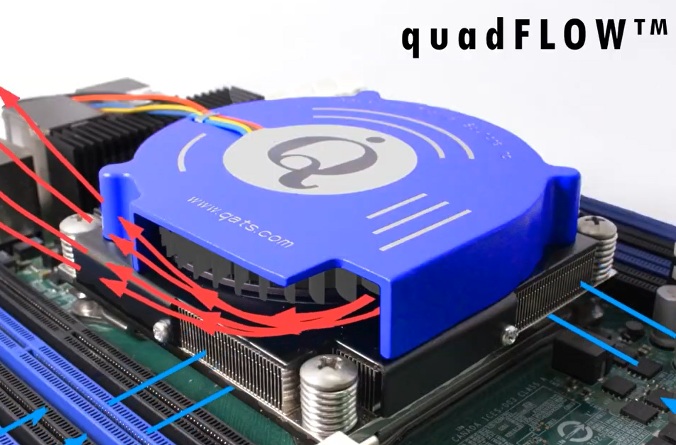
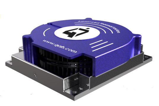
Figure 2 – A Heat Sink with High Performance, Top-Mounted Blower Designed for NVIDIA Jetson Thor Modules Provides 175W Cooling Capacity (Advanced Thermal Solutions, Inc.) [2]

Questions to Ask Before Choosing Air vs. Liquid

What is the deployment environment’s acoustic tolerance?

If the hardware sits in a windowless data center, segregated server room, or industrial telecom closet, definitely consider air cooling. The 70+ dBA noise of high RPM fans won’t matter there. If the component will be used in an office edge-server, a medical lab, or a workstation near human ears, choose a quieter cooling option, and certainly liquid cooling is one such choice.

What is the surrounding airflow topology and ducting design?

If a chassis allows for directed shrouding (baffles) to force intake air directly into a heat sink’s fin field, or if a blower can pull/push air through the sink from different sides, choose air. But if the PCB layout is cluttered, blocks airflow paths, or lacks a high-static pressure intake path, liquid cooling may be required to transport heat away via tubes.

Are you heading past the 250W–300W per-component barrier?

If you are cooling a 165W CPU or a 200W specialized accelerator, look into high-capacity air cooling systems to save on costs and eliminate leak risks. However, if the next-gen design will upgrade to a 400W+ AI processor, it would be more practical to design for liquid cooling early on. [3]

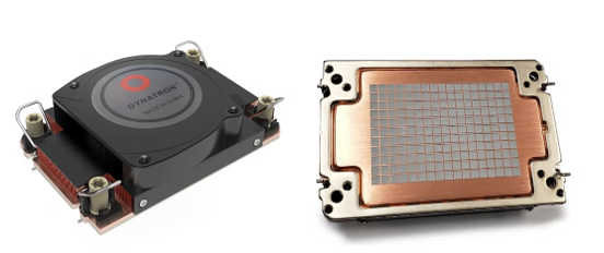
Figure 3 – A High-Capacity 1U Air Cooler with Vapor Chamber Base Designed for Intel Grand Rapids SP and Xeon 6 Processors. Its Fan Speeds Reach 8600 RPM and Cooling Performance Up to 330W. (Dynatron) [4]

Let’s compare elements of high-capacity air cooling with alternative liquid cooling [5]:

References

  1. Coolerguys, https://www.newegg.com/p/3C6-00VJ-000E6
  2. Advanced Thermal Solutions, Inc., https://www.qats.com/Products/High-Capacity-Air-Cooling#QFLOW
  3. ServerMall, https://servermall.com/blog/air-or-liquid-server-cooling-which-to-choose-in-2026/
  4. Dynatron, https://www.dynatron.co/product-page/s7-4710
  5. Asperitas, https://www.asperitas.com/post/air-cooling-direct-liquid-cooling-and-single-phase-immersion

Accurate Instruments are Essential When Measuring for Thermal Management Solutions

By collecting and analyzing more relevant measurement data, electronic cooling systems can be designed for improved performance, reliability, and cost. It’s essential these measurements be as accurate as possible. Critical data points include component temperature, air temperature, air flow rate, and often air pressure. Accuracy becomes even more important when performing accelerated testing as seen in this post.

Research-grade instruments and specialized sensors, properly calibrated and operated, can measure chip temperatures and surrounding elements, such as local airflow. Separate instruments can be used to quantify specific conditions, but more real-use data is obtained when all points are collected simultaneously. Taken over a range of time and conditions, simultaneous measurements provide more accurate, actionable information. They also reduce the cost and set-up time for multiple studies.

Fig 1 – Input Ports for a Laboratory Instrument that Simultaneously Measures Air Velocity, Temperature and Pressure. [ATS]
Fig 2 – High-quality Thermal Data Reduces Uncertainties in Cooling Solutions than Calculated Data. [ATS]

Accelerated Product Reliability Testing

Reliability testing at different temperatures and conditions is commonly performed to identify expected product life. When an electronic system is running, it continuously experiences temperature and power cycling. These fluctuations are typically normal, but should be factored into a comprehensive thermal profile study.

It’s not practical to wait years to see if a component fails. Accelerated life testing provides faster predictions. A commonly used predictive tool is the Arrhenius model shown below.

Accelerated life testing using the Arrhenius model is a method for predicting how long a product will last under normal conditions by running it at elevated temperatures for a shorter time. The temperature increase speeds up the same failure processes that would eventually occur in the field—compressing years of life into weeks of testing.

Accelerated life testing Arrhenius calculators can help estimate field lifetime, test duration, acceleration factors, activation energy, and field failure rates. These tools are useful when real-time qualification can’t be done. This is typical with electronic components and devices that need fast market introduction. One such calculator is found here: Accelerated Life Test Arrhenius Calculator. [1]

The Arrhenius Model handles pure thermal stress, while the Eyring Model includes temperature plus other active forces like humidity or voltage. [1,2]

Highly Accurate Thermal Instruments

Besides its design, a thermal instrument’s construction and calibration should be high quality, and not a source of more errors. Accurate, research-grade instruments are essential for valid engineering practices. Without them, reliability predictions for a new product are actually less reliable themselves.

Fig 3 – Candlestick Sensors are Thin Profile (0.5 mm) with a Small Base (9.5 mm dia) for Collecting Air Temperature and Velocity Data at Single or Multiple Locations. [ATS]
Fig 4 – Here, Air Temperature and Velocity Measurements are Taken Every Second by an eATVS-8 Instrument. stageVIEW Software Provides a Wide Range of Data Collection Choices. [ATS]


Here are some of the ATS instruments available for temperature and velocity measurement and providing the highest-quality thermal reliability test results.

Conclusion

Temperature has a significant effect on reaction rate and the subsequent reliability prediction. Small errors in temperature and airflow measurements can significantly impact reliability predictions. Such errors typically occur in the measurement process or from using inaccurate instruments.

If thermal data is inaccurate, outcomes can include over-designed systems, cost overruns, and products not shipping.

Laboratory-quality thermal instruments can reduce or eliminate measurement and calculation mistakes, leading to higher quality, faster to market and ultimately lower cost products. Just as important, collected data needs to be correctly interpreted. Expert thermal engineers can do just that with data provided or that they obtain themselves.

More information on these topics can be seen at these ATS videos:

How to Properly Measure Air Velocity in Electronic Systems [Link] [3]

How to Perform and Understand Temperature Measurement within Electronic Systems [Link] [4]

stageVIEW Software Demo [Link] [5]

References

  1. Firgelli Automations, https://www.firgelliauto.com/blogs/calculators/accelerated-life-test-arrhenius-calculator
  2. NIST, https://www.itl.nist.gov/div898/handbook/apr/section1/apr152.htm
  3. Advanced Thermal Solutions, Inc., https://vimeo.com/reviews/a4e9a72d-d228-489f-8edb-a98e440a8ef1/videos/113427506
  4. Advanced Thermal Solutions, Inc., https://vimeo.com/reviews/63784f1b-a32d-4f90-86b1-5bf362715619/videos/113432468
  5. Advanced Thermal Solutions, Inc., https://www.youtube.com/watch?v=Lx5NlAI5TuM

Technical Discussion: Designing Heat Sinks for Cooling QSFP Optical Transceivers

During a recent project designing a thermal solution for a customer’s PCB (printed circuit board) layout, Advanced Thermal Solutions, Inc. (ATS) Field Application Engineer Peter Konstatilakis also analyzed the thermal properties of a series of SFP (small form-factor pluggable) optical transceivers on the edge of the board.

QSFP Optical Transceivers

ATS engineer Peter Konstatilakis holds the heat sinks that he designed for cooling QSFP optical transceivers. (Advanced Thermal Solutions, Inc.)

From that project came the idea of examining the thermal challenges presented by SFP and QSFP (quad SFP) and designing a heat sink solution that future customers could use to solve potential issues that stem from the increased power requirements of the compact transceivers that are frequently used in the transmission of data.

After conducting an analytical analysis, running computer simulations, and testing the heat sinks in the state-of-the-art ATS labs, Peter demonstrated a new heat sink design and optimized layout sequence that showed 30 percent improvement on QSFP heat sinks currently on the market.

In addition, he showed that having heat sinks with fewer fins upstream and heat sinks with more fins downstream provided a near isothermal relationship between the first and last QSFP, an important consideration for QSFP arrangements.

Peter recently sat down with ATS Vice-President of Marketing and eCommerce Rebecca O’Day and Marketing Communications Specialist Josh Perry to discuss the project, his research, and the successful design of the new QSFP cooling solution.

JP: What prompted the work on QSFP heat sinks? Why did we start looking into this technology?
PK: Optics are pretty big now with all the higher information rates, 400 gigabyte cards, which is 400 gigabytes of throughput and that’s a lot. They need these multiple high-powered SFP or QSFP to do that. So, higher power demands call for ATS expertise in thermal management.

RO: Optics are really expanding. It’s not just routers and things like that, but they’re also used in storage, array networks, video…so this kind of thing could really be able to expand.
PK: Anywhere that you are transferring data, which is basically everywhere – the Cloud, big servers, the internet itself. They’re being used a ton.

JP: Was the impetus for designing QSFP heat sinks something that was prompted by a customer or did we think about the technology and recognize that it needed to be cooled?
PK: We had worked on SFP cooling for a customer first, so that helped us understand the area a bit more. Also, from what we were hearing from customers, QSFP that were being designed had higher throughput, which means higher power. And it is also good to have products that we can market, even if it isn’t for every customer, and show that we can handle the optical transceiver arena.

JP: What was the first step in designing the heat sinks? Did you know a lot about QSFP or did you have to do a lot of research?
PK: There is definitely a lot to think about. You can’t use a TIM (thermal interface material) because the QSFP isn’t fixed in the cage; it can be hot swapped. After a few insertions and removals, it will gunk up the TIM.

JP: Was that something you knew before?
PK: It was something I knew before, but there is also a specification document for this technology written by the SFF (Small Form Factor) Committee, which is a standard controlled document that engineers design to for this form factor and it stated in there not to use a TIM. When we looked at it with the customer, it made sense and when we asked the customer they agreed.

RO: If there is no TIM, how does the interface work? Is it a direct interface? Is it flat enough?
PK: You have to specify a good enough flatness and surface roughness, within cost means, that will still have a low contact resistance. That was one of the challenges as well as understanding the airflow of typical QSFP arrangements because you have four in a row, so you’re going to have preheated air going into the fourth QSFP.

JP: When designing the heat sinks, what were the issues that you needed to consider?
PK: One consideration was getting as much surface area as we can, so that required extending the heat sink off the edge of the cage and we also had fins on the bottom of the heat sink. Usually, you only have fins above the cage but there was some room underneath, about 10 mm depending on what components are around, which provides additional surface area.

We also found that when you extend the surface the spreading resistance becomes an issue as well, so you need to increase the thickness of the base to help spread the heat to the outer extremities of the heat sink. You want the first QSFP and the last QSFP case temperatures’ to be isothermal due to laser performance (an electrical parameter), whereas each individual heat sink should be isothermal to get the most out of all the heat sink surface area (a heat transfer parameter).

‘Cold’ spots insinuate a lack of heat transfer to that location and thus poor use of that surface area. Then it was about the airflow and having the front heat sinks be shorter with fewer fins and the back two to be taller with denser fin arrays.

ATS heat sinks designed specifically for cooling QSFP optical transceivers. (Advanced Thermal Solutions, Inc.)

JP: Was the difference in fin arrays between upstream and downstream heat sinks how you optimized the design to account for the preheated air?
PK: What is really important is to keep each QSFP at the same temperature, within reason, because they all work together. So, if one is a higher temperature than another, the laser performance is going to be affected and it will affect the stack. You want to have them as isothermal as you can; the case temperature from the first QSFP to the last.

We figured when we were going through the design, you could have a shorter heat sink up front with fewer fins to help the airflow pass to the downstream QSFP. The upstream QSFP wouldn’t need as much cooling because they’re getting the fresher air and faster airflow. So, if you relax the front heat sinks and make the ones in the back more aggressive, then you’re going to get better cooling downstream.

What happens is the front heat sinks aren’t as effective. This is fine as long as the upstream QSFP case temperatures are lower than the downstream QSFP. The overall effect is that the upstream QSFP temperatures will be closer to the temperature of the downstream QSFP, keeping the stack as isothermal as possible.

This is where the limit lies. Minimizing the upstream QSFP heat sinks, which in turn minimizes the amount of preheat to the downstream QSFP and allows as much airflow to enter downstream QSFP. At the same time ensuring the upstream QSFP temperatures are equal to or just lower than the downstream QSFP. This keeps the downstream QSFP temperatures at a minimum, while also keeping the transceiver stack close to isothermal.

JP: Were there any unexpected challenges that you had to account for?
PK: There was a challenge in testing and making sure that the thermocouples (which you can see in the picture below) contact the heat sink surface correctly and all of them at the same point. I had to glue it, so it may touch the case of the heat sink or it may not, depending on how the glue set, so I had to put a little thermal grease inside the pocket just to have the thermocouple make good contact with the heater block itself.

The test setup to measure cooling performance of individual heat sinks on a QSFP connector cage when airflow is from one side only. (Advanced Thermal Solutions, Inc.)

The metal piece (heater block) mimics the QSFP and we put a cartridge heater in the middle to heat it up and then we put a groove where the thermocouple is attached as I just explained.

Other than that…it was really just the flatness. It was hard to test and get reliable data between several heat sinks because there is going to be some flatness variation between them. Sometimes there isn’t enough to show a variation, but if I’m seeing different data with a different heat sink on the same heater block then the flatness and surface roughness is affecting it.

RO: On the flatness issue, in theory someone could spend a lot of money and make sure that it was completely flat but there’s a certain point where it has to be flat enough.
PK: Obviously there are diminishing returns after a certain point, so you have to find that line. There are no calculations that explain flatness and surface roughness, so at the end of the day it comes down to testing.

RO: I find it interesting that the testing was a challenge because it appears to us on the outside that this is a standard approach but then you get into it and have to ask how are we going to measure the temperature accurately:
PK: There is always something that comes up which you didn’t think about until you start doing the testing and you have to make a change and modify it to make it work. That is where experience comes in handy. The more testing you do, the more you’ve seen and you can take care of the problem before it arises.

RO: It’s a good example of what we can do at ATS. We don’t have to test with a full, expensive board or the full optical arrangement, instead we can come up with inexpensive (low startup cost) ways to test that will provide quick, accurate data to help the customer get to market.

JP: So, we tested three different arrangements for the heat sinks?
PK: Yeah. There were two different designs with changes in the density of the fins. Based on the CFD (computational fluid dynamics) and in the lab, the best outcome was having the less dense fins in front for the first two heat sinks and having the denser fin arrays downstream. As we expected, more airflow was able to make it to the back heat sinks and were able to cool them more effectively.

QSFP Heat Sinks

This graph shows the difference in temperature between the ATS heat sinks at various air flows. (Advanced Thermal Solutions, Inc.)

We were seeing less than a degree difference, especially at higher airflows, between the first heat sink and the last and that was pretty impressive. That configuration also provided the lowest temperature for the final two QSFP. Those are going to be the limiting factors; they’re going to be the highest temperature components no matter what since they’re receiving preheated air. That’s why it’s important to minimize the preheated air and maximize the airflow downstream by designing shorter, low fin-density heat sinks upstream.

If you put a dense heat sink up front, you’re going to restrict airflow downstream and you’re going to pull more heat out of the component because it is a better heat sink. With this you’re going to dump more heat into the air and send it to the downstream QSFP. So, it is worth keeping some heat in the upstream components, which has a double effect of keeping all of the QSFP temperatures as isothermal as possible. As long as the upstream components aren’t going over the case temperature of the last component, then you’re fine.

RO: It’s almost counter-intuitive. The general thermal design says to pull as much heat away from the component as quickly as possible and dissipate it, but you’re saying it was better to leave some of the heat in place.
PK: For the upstream QSFP, absolutely. There is margin because it is receiving so much fresh air.

That is really because we’re working in a system environment where choices upstream affect the airflow downstream. If it wasn’t a system and you’re looking at a single component, then sure you want to get rid of all the heat. And again, leaving heat in also allows the QSFP components to be as isothermal as possible.

JP: It sounds like it worked the way that you expected going in?
PK: Yeah it did. I’m not going to sit here and pretend it always happens that way but what we thought would happen did happen and we were able to design it analytically before we went into CFD and testing.

JP: Were there certain calculations that you use when working with a system?
PK: We can look at the fan curve. Each heat sink has its own pressure drop and the way you use a fan curve is to analyze the four heat sinks, add the pressure drops together, and then examine the fan curve (the amount of airflow varies with the pressure that the fan sees) with the higher the pressure, the less airflow. So, we’re able to estimate the amount of airflow across the system based on the total pressure drop.

We also use Q=mCpΔT and that way we can determine, based on the amount of power coming from the component, what is the air temperature that is leaving the heat sink. It is a little conservative because we’re saying that all of the heat is going into the next heat sink, which isn’t true because a little is escaping to other locations, but being conservative doesn’t make a difference when comparing designs.

Analyzing the airflow into each heat sink and the temperature into each heat sink lets us know what we have to design for; just because you’re putting more surface area doesn’t mean you have a good solution.

RO: This is a good example of how thermal management is more than just removing the heat, but also analyzing how the heat travels and thinking about it as a system. It’s much more complicated.

JP: How important is for ATS to be able to see potential thermal challenges in new technology, like this, and work through the problem even if it isn’t for a specific design or customer?
PK: It always helps to have more experience. It’s knowledge for the future. We’ve already seen it, we’ve already dealt with it, and we can save time and cost for the customer.

Whenever we run into this issue, we can say we tested that in the lab and explain the solution that we found. We don’t need to do more analysis, but provide the customer with a solution.

For more information about Advanced Thermal Solutions, Inc. (ATS) thermal management consulting and design services, visit https://www.qats.com/consulting or contact ATS at 781.769.2800 or [email protected].

Digital News Gets Support from ATS

With Thermal Engineer day approaching (7/24) we here at ATS would like to thank all of the PR firms and digital news magazines who covered our new clipKIT campaign.

thermal technology - digital news - electronics businessAs a token of our appreciation, we have provided a link to our customers and viewers to download our clipKIT data sheet for all your attachment needs. HERE.


Understanding Loop Heat Pipes

Looped heat pipes (LHPs) are two-phase heat transfer devices that employ the same capillary pumping of a working fluid as used in conventional heat pipes. LHPs can transfer heat efficiently up to several meters at any orientation in the gravity field. When placed horizontally, this distance can extend to several tens of meters.

The development of the LHP was driven mainly by a limit of conventional heat pipes in which the wick system abruptly decreases its heat transfer capacity, if the evaporator is raised higher than the condenser. This need was acutely felt in aerospace applications where the heat generated by the electronics had to be transferred efficiently away for dissipation purposes. But the device needed to be much less sensitive to changes in orientation in the gravity field. Figures 1a and 1b show the schematic of an LHP [1].

The development of looped heat pipes dates from 1972.    Qpedia_0508_Loop_Heat_Pipes_Figure1Figure 1. Schematic of Principle of Operation of a Loop Heat Pipe [1, 2].

The first such device, with a length of 1.2m, a capacity of about 1 kW, and water as its working fluid, was created and tested successfully by the Russian scientists Gerasimov and Maydanik from the Ural Polytechnic Institute. With heat needing to be transported over a longer distance, and because the working fluid circulation in a heat pipe is directly proportional to the surface tension coefficient and inversely proportional to the effective pore radius of the wick, a different system for heat transport was required when the evaporator was above the condenser. This is shown in Figure 1.

The capillary head must be increased to compensate for pressure losses when the liquid is moving to the evaporator while operating against gravity. This can only be done by decreasing the effective pore radius of the wick. However, the increase in hydraulic resistance is approximately proportional to the square of the pore radius. As a result, it has not been possible to build a heat pipe of sufficient length that is capable of operating efficiently against gravity. Thus, there was incentive to develop LHPs, and they are now finding further application in modern electronics.

As stated, a number of limits impact the performance of an LHP. Qing et. al. [3] performed a detailed investigation of three key parameters on the performance of a looped heat pipe for use in cryogenics applications. This LHP is shown in Figure 2.

1) Effect of Wick Pore Size – It is well known that the maximum capillary pressure produced by the primary wick depends on both the effective pore size and the surface tension of the working fluid. In general, the smaller the pore size and the larger the surface tension, the higher the maximum capillary pressure. A smaller pore size will also result in larger flow resistance which will limit heat transfer capability. The pore sizes considered were 2 and 10 μm.
Figure 2. Schematic of an LHP for Cryogenics Application [3].
When the pore size of the primary wick is larger (10mm), the heat transfer capability of the LHP can reach 26 W only when a smaller reservoir (60cc) is used. Its ability to operate against gravity is greatly weakened. With a wick pore size of 2mm, the LHP can transfer a heat load of 26 W under horizontal orientation no matter what size reservoir volume is used.

Qpedia_0508_Loop_Heat_Pipes_Figure2Figure 2. Schematic of an LHP for Cryogenics Application [3].

2. Effect of Reservoir Size – It is interesting to see how the LHP will function with different reservoir sizes. As shown in Figure 3, the combination of gravity and reservoir size has a direct impact on the heat transfer capability of the LHP. Under adverse gravity, the heat transfer capability of the LHP is 12 W using the larger reservoir and only 5W using the smaller one.Qpedia_0508_Loop_Heat_Pipes_Figure3
Figure 3. Heat Transfer Capability of LHPs with 2mm and 10mm Pore Diameters in Horizontal Orientation [3].

3. Effect of Working Fluid – Fluids have different surface tensions that impact the heat transport capability of the LHP.

Figure 4 demonstrates this capability: Qpedia_0508_Loop_Heat_Pipes_Figure4
Figure 4. Heat Transfer Capability of an LHP When the Working Fluid is Oxygen [3].

Though not shown in Figure 4, when the working fluid is oxygen instead of nitrogen, the heat transfer capability can be up to 50 W under horizontal orientation with the other experimental conditions remaining the same.

LHP Applications
This discussion has highlighted the functionality and importance of design parameters on the performance of LHPs. While this discussion concerns an aerospace application, LHPs have been used for standard electronics as well. Maydanik gives several examples where miniature LHPs are used for microelectronics [1]. Figure 5 shows the “use of flat disk-shaped evaporators in LHPs. The scheme and the external view of such evaporators 10 and 13mm
thick, whose thermo-contact surface is made in the form of a flange 45 mm in diameter for fixing the heat source. The results of development of ammonia LHPs 0.86m and 1m long with a vapor and a liquid line 2mm in diameter equipped with such evaporators of stainless steel. In trials the devices demonstrated serviceability at any orientations in 1-g conditions. The maximum capacity was, respectively, 90–110 W and 120–160 W, depending on the orientation, and the value of the minimum thermal resistance 0.30 K/W and 0.42 K/W.”

Qpedia_0508_Loop_Heat_Pipes_Figure5
Figure 5. Photo and Schematic of Flat, Disk-Shaped Evaporators in an LHP [1].

Another design is shown in Figure 6, where miniature LHPs are made from stainless steel and copper and the working fluids are ammonia and water . The ammonia LHP has a 5mm diameter evaporator with a titanium wick, and 2mm diameter lines for vapor and liquid.. The water LHP is equipped with a 6mm diameter evaporator and 2.5mm diameter lines. The effective length of the devices is about 300mm.

Qpedia_0508_Loop_Heat_Pipes_Figure6
Figure 6. Miniature LHPs [1].

Each has a finned condenser, 62mm long, whose total surface is about 400cm2. The condensers are cooled by a fan providing an air flow rate of 0.64 m3/min, at a temperature of 22 ± 2°C.
Tests show that the maximum capacity of the ammonia LHP is 95 W at an evaporator wall temperature of 93°C. The maximum capacity for the water LHP was not achieved, but at the same temperature it was equal to 130 W. The minimum thermal resistance values of the LHP, 0.12 K/W and 0.1K/W, were obtained at heat loads of 70 W and 130 W, respectively. It should be noted that the ammonia LHP demonstrated a higher value of for heat transfer coefficient in the evaporator, which reached 78,000 W/m2K at a heat flow density of 21.2 W/cm2 at the surface of an interface with an area of 4 cm2. For the water LHP, these values were, respectively, 31,700 W/m2K and 35 W/cm2. In this case, at the surface of the evaporator’s active zone, the heat flow density was much higher. For the ammonia LHP it was 44.5 W/cm2, and for the water was 69.1 W/cm2 [3].

Qpedia_0508_Loop_Heat_Pipes_Figure7
Figure 7. Photo and Schematic of a CPU Cooler Based on an LHP [4, 5].

Another example of LHPs in microelectronics is shown in Figure 7. Here, an LHP was designed for cooling a 25-30 W processor with a total weight of 50g. This LHP was based on copper-water with an evaporator diameter of 6mm.
In conclusion, LHPs may resolve many of the drawbacks seen in conventional heat pipes and provide additional capabilities. As shown by Maydanik, the capillary mechanism, in conjunction with the reservoir size and the use of different fluids, can bring significant advantages that may not readily be seen in heat pipes. Some of these include:

  • the use of fine-pored wicks,
  • maximum decrease in the distance of the liquid motion in the wick,
  • organization of effective heat exchange during the evaporation and condensation of a working fluid, and,
  • maximum decrease in pressure losses in the transportation (adiabatic) section.

Along with the advantages gained from LHPs, the use of liquids in electronics and potential operational instability must be considered carefully. Operational instability, if not managed, could conceivably create thermal cycling on the electronics component being cooled. As with heat pipes,operational dry out or the loss of fluid due to leakage could render the LHP inoperable. Otherwise, LHPs appear to be an attractive supplement to the arsenal of cooling options available to the design engineer. ■

References:
1. Maydanik, Y.., Loop Heat Pipes, Applied Thermal Engineering, 2005.
2. Muraoka, I., Ramos, F., Vlassov, V., Analysis of the Operational Characteristics and Limits of a Loop Heat Pipe with Porous Element in the Condenser, International Journal of Heat and Mass Transfer, V44, 2001.
3. Mo, Q., Jingtao, L., Jinghui, C., Investigation of the Effects of Three Key Parameters on the Heat Transfer Capability of a CLHP, Cryogenics V47, 2007.
4. Chang, C., Huang, B., Maydanik, Y., Feasibility of a Mini LHP for CPU Cooling of a Notebook PC, Proc. of 12th Int. Heat Pipe Conference, Moscow, Russia, May 2002.
5. Pastukhov, V., Maydanik, Y., Vershinin, C., Korukov, M., Miniature Loop Heat Pipes for Electronic Cooling

round or flat heat pipes for electronics coolingHow to subscribe to qpedia