Author Archives: Norm Quesnel

Tubed Cold Plates: Balancing Thermal Performance, Reliability, and Cost


Tubed cold plates provide a reliable, cost-effective liquid cooling solution when air cooling can no longer dissipate the required heat load. They typically consist of an aluminum plate with embedded copper or stainless-steel tubing. Heat-generating electronic components are mounted directly to the plate, allowing heat to conduct into the tubing where a circulating coolant—typically water or a water-glycol mixture—absorbs it. The heated coolant then flows to a heat exchanger or chiller before returning to the cold plate to repeat the cycle. [1-5]

Fig 1 – A Tubed Cold Plate Requires a Complete Liquid Loop to Function. Other Loop Components Include a Liquid Reservoir, a Pump, and a Heat Exchanger. [6]

As with most liquid cooling systems, increasing coolant flow rate reduces the thermal resistance between the electronic components and the coolant, improving overall heat transfer performance. For example, with coolant flowing at 1.9 LPM (liters per minutes) one copper-tube cold plate provides thermal resistance of 0.013°C/W. When the flow rate increases to 7.6 LPM, the resistance drops to 0.007°C/W. Continuous copper and steel tubing readily manages high flow rates.

Thermal performance depends on several design variables, including tube material (typically copper or stainless steel), the tube attachment method, and the coolant flow path. Together, these factors determine whether a tubed cold plate is appropriate for the required heat load, coolant chemistry, and operating pressure. [7-11]

Embedding the Tube

The tube is continuous, without joints, which eliminates leak threats and allows it to be bent into serpentine patterns to optimize the plate’s performance.

The method used to attach the tubing to the cold plate has a significant influence on thermal performance. [12,13]

  • Pressed-In (Epoxy Mounted): The tube is pressed into pre-machined grooves on the plate and secured with a thermally conductive epoxy. This is cost-effective but introduces a slight thermal barrier. [14,15]
  • Direct Contact: The embedded tube is machined flat so it sits perfectly flush with the plate surface. The electronic component touches the tube directly, maximizing heat transfer. [16,17]
  • Soldered/Brazed: The tube is metallurgically bonded to the plate. This offers the best thermal performance for tubed designs but increases manufacturing costs. [18]
Fig 2 – (Left) Copper Tube Embedded in Thermally Conductive Epoxy. The Epoxy Improves Heat Transfer to the Aluminum Plate and Keeps Out Potential Insulators, (Right) Press-Fit Copper Tube Provides Secure, Continuous Direct Contact with the Plate. [11]

Tubed Cold Plate – Application Example

Tubed cold plates provide cooling to components with low to moderate heat loads. They are used in thousands of commercial, industrial and military electronics devices. Industry standards for tubing and connectors, and relatively simple construction, provide the flexibility to fit many applications.One example is an ultra-wideband radar subarray consisting of clustered amplifier and analog electronics operating across ambient temperatures ranging from –18°C to 46°C. Air cooling was initially evaluated, but the required heat sink length and high system airflow pressure made that approach impractical. A liquid-cooled tubed cold plate provided the required thermal performance while meeting system constraints.

Fig 3 – (Top) Conjoined Cold Plates Cool the Analog and Amplifier Board Sections on Radar Device. Added Tube Turns Optimize Cooling of the Hotter Amplifier Components. (Bottom) CFD Model with 75W Power in the Amplified and a 12 GPM Flow Rate Showed Achievement of Target Cooling Performance [19]

ATS developed dual tubed cold plates for the amplifier and analog assemblies using standard 0.25-inch (6.35 mm OD) tubing arranged in a multi-pass serpentine configuration. The geometry was optimized to balance heat transfer, pressure drop, and manufacturability. The cold plates were modeled in series with push-to-connect manifold integration. Because of the resulting hydraulic resistance, a higher-capacity pump was required to achieve the desired coolant flow rate. [19]

This tubed cold plate application used thermal engineering methods that integrated CFD and system-level flow modeling, including pump curve interaction. Both thermal and hydraulic performance were optimized, Standard tube and cold plate geometries were used, enabling rapid, lower cost production and scalability.

More Tube Turns Increase Heat Transfer

Increasing the number of tube passes generally improves heat transfer by increasing the tubing surface area available for conduction and by distributing coolant beneath a larger portion of the plate. The result is lower peak temperatures and improved temperature uniformity across the mounting surface.

But there is a limit to the benefits from added tube turns. While they capture more heat, a high number of turns increases fluid friction and hydraulic resistance (pressure drop) inside the cold plate. As with the example above, a more powerful pump may be needed. [20,21]

Fig 4 – The More a Tube is Coiled in a Cold Plate, the More Surface Area is Available for Mounting Hot Components. But There are Limitations. [22]

Another issue is the rise in coolant temperature. As it travels through a complex pathway in the cold plate it will absorb so much heat that it can’t absorb more.  Because the fluid is now warm, those extra turns at the end of the loop transfer heat much less efficiently than the first few turns. [23,24]

Figure 5 – An Aluminum Cold Plate with Four-Pass, Three-Turn Stainless Steel Tubing. [25]

Summary

Tubed cold plates remain one of the most widely used liquid cooling technologies because they combine proven reliability, relatively low manufacturing cost, and robust mechanical performance. Their continuous tubing construction minimizes leak paths while allowing operation at higher coolant pressures than many alternative cold plate designs.

  • Because they use continuous tubing, they have zero internal joints, making them highly reliable for sensitive electronics.
  • There are material choices to fit different applications. For example, you can use an affordable aluminum plate for structure, but a copper tube inside to handle corrosive water coolants without galvanic corrosion.
  • They are generally much cheaper to manufacture than vacuum-brazed or micro-channel cold plates.
  • And the inherent strength of metal tubing allows these plates to handle high fluid pressures. [26]

Are there limitations? Yes.

  • There are limits on how tightly a metal tube can be bent without crimping or restricting fluid flow. [3
  • More tube passes can improve heat transfer and temperature uniformity, but too many passes increase pressure drop and reduce efficiency as the coolant warms.
  • Also, cold plates have higher thermal resistance than vacuum-brazed or micro-channel cold plates because the heat must travel through the plate-to-tube interface.

References

  1. ElePCB, https://www.elepcb.com/blog/pcb-thermal-management/
  2. Medical Design Briefs, https://www.medicaldesignbriefs.com/component/content/article/23309-thermal-design-considerations-for-medical-devices-to-improve-patient-safety
  3. Mersen, https://www.mersen.com/en/products/cooling-solutions-services/right-fluid-liquid-cold-plates
  4. Guchen, https://www.guchen.com/battery-solutions/liquid-cold-plates.html
  5. Cooling Source Thermal, https://coolingsourcethermal.com/liquid-cold-plates/
  6. Advanced Thermal Solutions, Inc., https://www.qats.com/cms/tag/cold-plates-2/
  7. Advanced Thermal Solutions, Inc., https://www.qats.com/Products/Liquid-Cooling/Tubed-Cold-Plates
  8. Radian, https://radianheatsinks.com/liquid-cold-plates/
  9. Jiga, https://jiga.io/articles/cold-plate/
  10. Intergalactic, https://ig.space/commslink/cold-plates-and-conductive-cooling-a-brief-overview
  11. Trumony Techs, https://www.trumonytechs.com/what-are-cold-plates/
  12. Advanced Thermal Solutions, Inc., https://www.qats.com/qpedia/qpedia-issue103-1-0319.ashx
  13. LinkedIn, https://www.linkedin.com/pulse/fundamentals-liquid-cold-plate-cooling-igbt-modules-amar-vishal-5cxxe/
  14. D6 Industries, https://d6industries.com/capabilities/technologies/
  15. ITS Cooling, https://www.itscooling.com/pages/solutions
  16. Baknor Thermal, https://www.baknorthermal.com/flat-copper-tube-liquid-cold-plate-to-dissipate-heat-from-power-electronics/
  17. Kaytus, https://www.kaytus.com/techpedia/13752.html
  18. Kenfa, https://www.kenfatech.com/liquid-cold-plate-thermal-management-guide/
  19. Advanced Thermal Solutions, Inc., https://www.qats.com/Learning-Hub/Case-Studies/High-Power-Liquid-Cooling-Architecture-for-Radar-Subarray-Electronics
  20.  Science Direct, https://www.sciencedirect.com/science/article/abs/pii/S073519332200700X
  21. Calgavin, https://www.calgavin.com/articles/heat-exchangers-for-batch-reactors
  22. AMS Technologies, https://shop.amstechnologies.com/Products/Thermal-Management/Liquid-Cooling-Components/Cold-Plates/
  23. HRS, https://www.hrs-heatexchangers.com/news/specify-heat-exchanger/
  24. JayzTwoCents, https://www.youtube.com/watch?v=RnPB_q51iVk
  25. AMS Technologies, https://shop.amstechnologies.com/CP10G21-Aluminum-Cold-Plate-with-4-Pass-Stainless-Steel-tube-beaded-fittings/C008684-6
  26. KingKa, https://www.kingkatech.com/what-are-the-top-5-liquid-cold-plate-technologies-and-which-one-is-right-for-your-application.html

Making the Change

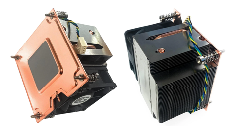
Air cooling was once the dominant method for cooling processors on a PCB, employing heat sinks, fans, and blowers. These solutions are still popular, but faster-running, higher-powered devices, like most GPUs used for AI can’t be sufficiently cooled with air. Liquid cooling is needed. [1,7]

There isn’t a universal application point where engineers must switch from air cooling to liquid cooling. The decision mainly depends on allowable temperature and heat flux. Other considerations include higher costs and power needs, added hardware, space and weight, and required more monitoring. [1,3]

Fig 1 – Air Cooling Heat Sink vs. Liquid Cooling. [9,10]

In practice, once devices reach several hundred watts in a compact package, or when the required thermal resistance approaches 0.1°C/W or lower, liquid cooling often becomes the preferred solution.

Low Thermal Resistance

Engineers usually don’t switch to liquid cooling simply because a chip reaches a particular wattage. They switch when the required junction-to-ambient thermal resistance falls below what can be achieved economically and reliably with available airflow and heat sink models. [2,3,5]

Fig 2 – Typical Chip Temperature Location [11]

Consider an equation and example:

Tj = Tα+ P x RαJA                              [2]

Where:

Tj = junction temperature

Tα = ambient temperature

P = power dissipation

RαJA = thermal resistance from junction to ambient

If keeping the chip within its temperature limits requires an unrealistically low thermal resistance, air cooling may not be practical.

Example:

Ambient = 40°C

Maximum junction temp = 90°C

Chip power = 500 W

The allowable thermal resistance is:

RαJA = 90 – 40 /500 = 0.1°C/W

Achieving 0.1°C/W with air is extremely difficult. Liquid cooling is the practical solution. [2,3]

High Heat Flux

Heat flux (power per unit area) is often more important than total power. [3]

For example:

  • A 100 W device spread onto a large heat sink may be easy to air-cool
  • A 100 W device concentrated in a 1 cm² die can be much harder

Modern high-performance processors, GPUs, laser diodes, RF power amplifiers, and power electronics often reach heat fluxes that make air cooling difficult.

Fig 3 – Heat Flux Measures the Amount of Heat Energy Transferred from a Warmer Side to a Cooler Side. [12]

Typical industry guidance suggests:

  • Air cooling: comfortable below ~10–20 W/cm² [1,6]
  • Advanced air cooling: can sometimes handle 50–100 W/cm² with aggressive airflow [1,6]
  • Liquid cooling: often becomes attractive above ~100 W/cm² [1,6,7]

In basic terms:

  • Air cooling is usually limited by how much heat you can transfer from the heat sink to the air.
  • Liquid cooling is usually limited by how much heat you can get from the chip into the coolant.

Where Air Cooling Works Well

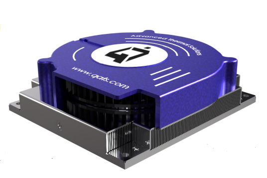
Fig 4 – Heat Sinks from Advanced Thermal Solutions, Inc. [9]

  • Total heat dissipation is relatively modest, up to a few hundred watts
  • There is enough surface area for heat sinks
  • There is sufficient airflow through the enclosure
  • Higher fan noise is acceptable  [1,3]

Air cooling is used in many consumer electronics products and networking devices.

Coolants Remove More Heat

Since water-based coolants have much higher heat capacity and thermal conductivity than air, they can transport large amounts of heat away with relatively small temperature rises. [3,9]

For example:

  • Air’s specific heat capacity is about 1 kJ/kg·K 
  • Water’s is about 4.2 kJ/kg·K   

And water is about 830 times denser than air, so a small coolant flow can carry away an enormous amount of heat compared with an equivalent volume flow of air. [9]

Fig 5 – Tubing and Ports on a Liquid Cooling System [9]

That’s why modern AI accelerators, high-power motor drives, and high-density data-center servers are increasingly moving toward liquid cooling: not because air cooling is impossible, but because the required heat removal density becomes impractical with fans and heat sinks alone. [1,7,8]

The Benefits of Faster Flow Rates

Air cooling performance increases when the rate of airflow increases. Thus, many heat sinks are supported with fans and blowers to enhance heat transfer into the passing air. [3]

Liquid cooling, similarly, is enhanced with higher flow rates. A common expectation is that a coolant that stays longer at the heat source (chip) will absorb more heat. But, at slower flow rates, the coolant heats up as it moves through a cold plate and downstream in the cooling loop. As a result, the returning coolant has less of a temperature difference from the chip, and heat transfer becomes less effective. [3,4]

With a faster flow of liquid coolant, the fluid temperature stays more uniform and keeps a steady, higher temperature difference from the chip. This makes heat extraction more efficient and improves the lowering of chip temperatures. [3,4]

Flow rates can be optimized per application. There are diminishing returns on performance as flow rates increase, as well as added costs. Your liquid cooling system provider should provide performance data and recommendations for proper flow rates. [3,4]

In-Between Air and Liquid Cooling

There are options that fall between air and liquid cooling methods. Engineers should look through these choices before designing in a liquid system. They could provide simpler, lower-cost, but reliably effective cooling       

The expanded options include:

  1. Better PCB thermal design (thermal vias, thicker copper planes)
  2. Larger heat sinks
  3. Forced-air cooling with optimized airflow paths
  4. Heat pipes or vapor chambers to spread heat
  5. Remote heat exchangers connected by heat pipes
  6. Liquid cold plates       [3,4]

Fig 6 – Heat Pipes May Meet Cooling Needs in Place of Air or Liquid Cooling [9]

Not a Tradeoff

Traditional air cooling is inadequate for many of today’s thermal management needs. Other methods, including enhanced air cooling  systems, may offer solutions. But for many applications, including fast-growing AI units and data centers, liquid cooling is essential. In this case, there is no tradeoff because its use is the only option. [1,6,7]

Consider This

Here are some analogies for comparing air to liquid (water) cooling:

Air is a ghost. Because air is so light and empty, a single cubic meter of it can only grab a tiny handful of heat before it gets too hot and gives up.

Water is a sponge. Because water is about 830 times denser and packed tight with mass, that same one cubic meter acts like a massive thermal sponge. It can swallow up a staggering amount of heat before its temperature rises even a single degree.

To cool a hot system, you either have to blow a hurricane of lightweight air past it, or gently glide a tiny, heavy stream of water over it.

References

  1. ASHRAE. Thermal Guidelines for Data Processing Environments, latest edition.
  2. JEDEC Solid State Technology Association. JESD51 Series: Methodology for the Thermal Measurement of Component Packages.
  3. Frank P. Incropera, David P. DeWitt, Theodore L. Bergman, and Adrienne S. Lavine. Fundamentals of Heat and Mass Transfer, Wiley.
  4. David A. Reay, Ryan McGlen, and Peter Kew. Heat Pipes: Theory, Design and Applications.
  5. Texas Instruments. Thermal Design by Insight, Not Hindsight (Application Report).
  6. Open Compute Project Foundation. Advanced Cooling Solutions documentation.
  7. NVIDIA. Data Center Liquid Cooling technical papers and deployment guides.
  8. National Institute of Standards and Technology (NIST). Thermophysical Properties of Fluids Database.
  9. Advanced Thermal Solutions, Inc., https://www.qats.com
  10. Chatsworth Products, https://www.chatsworth.com/en-us/resources/blogs/2026/5-misunderstood-facts-about-direct-to-chip-liquid-cooling/
  11. Advanced Thermal Solutions, Inc, https://www.qats.com/
  12. EngineerExcel, https://engineerexcel.com/flow-of-heat/

Extruded, Skived or Zipper Fin Heat Sinks

Which is Right for Your Design?

Compare extruded, skived, and zipper fin heat sinks to find the best thermal management solution for electronics, telecom, AI, and power applications.

As power densities continue to increase in electronics, thermal management has become a critical design consideration. Selecting the right heat sink technology can significantly impact system performance, reliability, size, and cost.

Let’s look at the differences between these heat sink technologies and provide guidance on where each solution performs best.

Extruded Heat Sinks

Extruded heat sinks are manufactured by forcing heated aluminum through a shaped die, creating a continuous profile that can be cut to desired lengths. This process produces an integral structure where the base and fins are formed from a single piece of material. [1]

Advantages

  • Lowest manufacturing cost for medium-to-high volume production
  • Excellent mechanical strength due to one-piece construction
  • Wide availability and short lead times
  • Lightweight and corrosion-resistant
  • Suitable for many general-purpose cooling applications

Fig 1 – Extruded Aluminum Heat Sinks are Produced in Continuous Profiles to be Cut to Desired Lengths. [2,3]

Limitations

  • Fin height and fin density are limited by extrusion tooling constraints
  • Typically manufactured from aluminum alloys only
  • Lower thermal performance compared to advanced fin technologies
  • Less effective in high-power or space-constrained designs

Best Applications for Extruded Heat Sinks include:

  • Industrial controls
  • Power supplies
  • LED lighting systems
  • Telecommunications equipment
  • Consumer electronics
  • Moderate-power electronics with natural or forced-air cooling

When cost, simplicity, and manufacturability are primary concerns, extruded heat sinks often provide the best overall value.

Skived Fin Heat Sinks

Skived heat sinks are produced by slicing thin layers of material from a solid metal block and bending them upward to form fins. Because the fins remain attached to the base material, the resulting structure maintains excellent thermal conductivity.

Both aluminum and copper can be used, with copper skived heat sinks offering particularly high thermal performance. [4,5]

Advantages

  • Higher fin density than extrusion
  • Taller, thinner fins improve heat transfer
  • No thermal interface between fins and base
  • Excellent thermal conductivity
  • Can be manufactured from copper for demanding applications

Fig 2 –  Skived Heat Sinks are Produced by Slicing Thin Layers from a Solid Metal Block and Bending Them to Form Fins. [6,7]

Limitations

  • Higher manufacturing cost than extrusions
  • More complex fabrication process
  • Practical limits on fin geometry still exist
  • Heavier when copper is used

Applications that Skived heat sinks excel in:

  • High-performance computing
  • CPUs and GPUs
  • Networking equipment
  • Power conversion systems
  • Medical electronics
  • Aerospace and defense electronics

Designers often select skived heat sinks when thermal performance requirements exceed the capabilities of traditional extrusions but a bonded-fin assembly is unnecessary.

Zipper Fin Heat Sinks

Zipper fin heat sinks use individually stamped metal fins that are mechanically interlocked into grooves in a base plate. The fins resemble the teeth of a zipper, giving the technology its name. This manufacturing approach allows extremely high fin densities and flexible fin geometries that are difficult or impossible to achieve through extrusion or skiving. [8]

Advantages

  • Extremely high fin density
  • Excellent airflow utilization
  • Can be integrated with heat pipes
  • Flexible fin shapes and configurations
  • Available in aluminum, copper, or mixed-material designs
  • Ideal for forced-air cooling applications
  • Supports large cooling surface areas in compact footprints

Figure 3 – Zipper Fin Heat Sinks use Individually Stamped Metal Fins Interlocked into a Base Plate, Shown Here with Integral Heat Pipes. [9,10]

Limitations

  • Higher manufacturing complexity
  • More expensive than standard extrusions
  • Thermal resistance at fin-to-base interfaces can be slightly higher than monolithic designs
  • Typically optimized for systems with active airflow

Zipper fin heat sinks are commonly used in:

  • Data center servers
  • AI and HPC systems
  • Telecom infrastructure
  • Base stations
  • Enterprise networking equipment
  • High-power FPGA and ASIC applications

Whenever maximum cooling performance is required in a constrained space with forced airflow available, zipper fin heat sinks are often the preferred solution.

Key Considerations and Performances of Heat Sink Types

The optimal choice depends on thermal requirements, available space, airflow conditions, and budget. [11,12]

Choose an Extruded heat sink when:

  • Cost is a primary concern
  • Thermal loads are moderate
  • Standard profiles meet design requirements
  • Production volumes are high

Choose a Skived heat sink when:

  • Higher thermal performance is needed
  • Increased fin density is beneficial
  • Copper construction is desirable
  • Space is limited but airflow may be moderate

Choose a Zipper Fin heat sink when:

  • Maximum cooling performance is required
  • Forced airflow is available
  • Fin density must be maximized
  • Thermal constraints are severe

Summary

No single heat sink technology can provide every electronic cooling solution. Extruded heat sinks remain the most economical solution for many designs, while skived heat sinks offer improved thermal performance through higher fin densities and superior material options. For the most demanding thermal challenges, zipper fin heat sinks provide exceptional cooling capability and design flexibility.

Ultimately, the ideal heat sink is one that satisfies thermal requirements while meeting mechanical, manufacturing, and economic objectives. By carefully evaluating airflow, thermal load, space constraints, materials, and cost, engineers can select the most effective thermal management solution for their specific application.

References

  1. Eaton, https://www.eaton.com/us/en-us/catalog/thermal-management-solutions/aluminum-extrusion-profiles.html
  2. Rapid Direct, https://www.youtube.com/watch?v=nIcYV1lDs2w
  3. Davantech, https://www.davantech.com/milling-customized-extruded-aluminum-heatsinks-precision-manufacturing-for-efficient-heat-dissipation/
  4. KenFa Tech, https://www.kenfatech.com/skived-vs-extruded-heat-sink/
  5. Kimsen, https://kimsenglobal.com/skived-fin-heat-sink-technical-deep-dive-for-engineers/
  6. Wekiko-Bythermal, https://www.youtube.com/shorts/RzM_fObq4w0
  7. Heatell, https://www.heatell.com/skived-fin-heat-sink/?utm_source=chatgpt.com
  8. Eaton, https://www.eaton.com/us/en-us/products/thermal-management-solutions/materials-finishes/zipper-tech-overview.html
  9. Gito Machine, https://www.youtube.com/shorts/_JJR477bHjQ
  10. Advanced Thermal Solutions, Inc., https://www.qats.com/Heat-Sinks/Zipper-Fin
  11. Boyd, https://info.boydcorp.com/hubfs/Resources/Resource-Center/Boyd-Guide-to-Heat-Sink-Fabrications-2020-Technical-Paper.pdf
  12. KingKa Tech, https://www.kingkatech.com/Skived-Vs-Extruded-Heat-Sinks-What-Are-The-Key-Differences-id48217376.html

The Importance of Thermal Management

Excess heat has affected electronic devices since their earliest days, becoming more critical with the advent of integrated circuits. Today, excess heat impacts the reliability, performance, and lifespan of devices and circuits across all applications. Common impacts of excess heat in electronics are:

Overheating: This can cause sudden shutdowns or failures. Elevated temperatures damage internal components, leading to permanent failure and potential safety risks—especially in high-power systems such as batteries and automotive electronics.

Lower performance: Overheating devices often throttle to reduce heat, and signal integrity may degrade, resulting in reduced performance. Maintaining operation within the designated temperature range lowers electrical resistance and power consumption while improving energy efficiency.

Shorter lifespans: High temperatures cause differential material expansion and deformation, damaging component structures and internal connections.

Thermal issues can also lead to field recalls and warranty claims. Dense PCB layouts may introduce thermal coupling between components, compounding heat-related risks.

Best practice is to engage thermal management specialists early. Effective thermal management controls and dissipates heat to maintain safe operating temperatures. Cooling solutions vary widely, but viable approaches exist for nearly every application.

Applying Professional Thermal Design

Effective cooling solutions require rigorous analysis at the concept stage, development, and testing. The thermal design process includes analytical modeling, experimental validation, and computational simulation across the full packaging domain—components, PCBs, shelves, chassis, and system enclosures.

Figure 1. CFD Simulation of Forced Airflow Across Areas of a Populated PCB.

Robust thermal design leverages both experimental and computational methods, using lab instrumentation and CFD tools such as FloTHERM, CFdesign, and Icepak, among other commercially available tools.

Empirical methods may include airflow or liquid testing, with measurements of velocity, temperature, and pressure, along with thermography using IR or liquid crystal techniques.

A disciplined, methodical approach consistently delivers strong results across diverse cooling challenges. OEMs can often avoid costly redesigns or recalls through expert thermal review, whether on-demand or via ongoing engineering partnerships. Subscription-based thermal services further accelerate validation and integrate thermal considerations earlier in development. More on these below.

Following are examples of carefully applied cooling design methodology.

Dual-Environment Thermal Analysis of a Sealed Offshore Electronics Enclosure

After detailed analytical modeling to envelop the solutions, CFD analysis was performed on a sealed offshore aquaculture enclosure operating in two passive environments: submerged seawater at 30°C and outdoor air at 40°C. The objective was to determine whether passive cooling could maintain component temperatures below 60°C.

Figure 2. (left) Outer Enclosure Temperature Contours. (center) An Internal Aluminum Sled to Transfer Component Heat to the Outer Enclosure. (right) Velocity Vectors Indicate the Slow Motion of the Internal Air.

The analysis showed the passive design was insufficient for the outdoor air case. Key limitations included weak natural convection and poor internal conduction to the enclosure walls. Hot spot spreading resistance significantly contributed to overall temperature rise.

Addressing the air case would also resolve the submerged case. Recommended improvements:

  1. Increase external surface area with fins or a bonded heat sink
  2. Improve internal conduction and reduce interface resistance
  3. Integrate heat pipes or vapor chambers to reduce spreading resistance

Multi-Cold-Plate Liquid Cooling System Design and Optimization

An EV battery manufacturer developed a 4 kW liquid cooling system with four cold plates integrated into a loop including a heat exchanger, DC-DC converter, and onboard charger. The design required balancing thermal performance, manufacturability, and flow distribution.

Figure 3. Four Cold Plates Receive Chilled Coolant from a Heat Exchanger as Part of a Liquid Loop that Included a DC-DC Converter and On-board Charger.

ATS combined analytical modeling with CFD to optimize cold plate geometry and system flow. Key parameters included tube routing, thermal resistance, and pressure drop.

Figure 4. CFD Simulation of a Revised Cold Plate with 10 Tube Passes and 9 Tube Bends.

A 10-pass serpentine tube design maximized heat transfer while maintaining acceptable pressure drop and manufacturability. Additional improvements included optimized tube diameters and balanced manifold routing.

The study demonstrated that effective kilowatt-scale liquid cooling requires coordinated optimization of geometry, pressure drop, and flow distribution. General findings:

  1. Balanced conduction and convection are critical
  2. Targeted passive changes can yield significant gains
  3. System-level optimization outperforms isolated fixes

CFD-Driven Thermal De-Risking of a Ruggedized Rack System

A baseline-to-optimization CFD study was conducted on a sealed 241 W ruggedized rack system with a 55°C ambient limit. The goal was to identify thermal violations and develop a reliable cooling strategy.

Figure 5. CFD Baseline Model and Surface Temperature Contours of a Ruggedized Rack System.

Through iterative CFD-driven design changes, ATS improved airflow efficiency, heat sink performance, and heat routing. Final modifications included revised heat pipe routing, heat sink replacement, fan reconfiguration, and removal of airflow obstructions. All components achieved thermal compliance.

Figure 6. Surface Temperature Contours of the System’s (left) Original Pin-Fin Heat Sink, and Its Replacement (right) maxiFLOW Heat Sink.

The study showed that sealed systems require holistic optimization across airflow, heat flow routing, fan placement, and heat sink design. General findings:

  1. Analytical modeling identified areas requiring attention and possible solutions
  2. Baseline CFD validated the findings in ‘1’ and identified thermal risks before failure
  3. Heat sink upgrades alone are insufficient without airflow optimization
  4. Iterative CFD enables targeted, low-risk refinement
  5. Final designs improve both compliance and thermal margin

Thermal Optimization of a Passive Aluminum Enclosure

ATS evaluated a sealed passive aluminum enclosure dissipating 75.8 W at 25°C ambient. CFD and parametric analysis identified key thermal constraints and guided optimization.

Figure 7. (left) Distribution of Enclosure Components, (right) Enclosure Baseline Thermal Distribution CFD.

Using 3D CFD with conjugate heat transfer, ATS modeled conduction and natural convection. Results showed that achieving target performance required coordinated improvements across both mechanisms.

Enhancements included improved thermal interface materials, better heat spreading, optimized fin geometry, reduced obstructions, and added vent gaps to enhance natural convection pathways.

Figure 8. The Enclosure Thermal Optimization Included Adding Cross-Cut Venting Gaps to Optimize Natural Convection.

Passive cooling performance is governed by the interaction of internal conduction and external convection. Key limitations included interface resistance and restricted airflow, with diminishing returns from geometry-only changes. Findings:

  1. Balanced conduction and convection are essential
  2. Targeted passive improvements deliver measurable gains
  3. System-level optimization is more effective than isolated changes

Conclusion

Modern electronics—including AI hardware—generate substantial heat loads, making thermal management a first-order design constraint. Large-scale systems such as data centers incorporate cooling from the outset, but thermal design is equally critical at smaller scales.

Figure 9. ATS Thermal Engineers Use Thermochromic Liquid Crystals to Reveal Hot Spots in Electronic Devices. See a Demonstration Video: https://www.youtube.com/watch?v=peewxRlNVqg

Every application presents unique challenges, and thousands of new devices each year require tailored cooling solutions.

When clients have excess heat issues, ATS engineers work closely with them to deliver cost-optimized, practical thermal and mechanical solutions that align with real-world schedules. The objective is consistent: deliver the right solution the first time.

For OEMs and others with continuing needs for thermal engineering, ATS now provides a subscription service. This comes with tiered support levels, ranging from periodic consultation to embedded engineering support within development teams. Contact ATS for more information on the thermal engineering subscription service.

Figure 10. ATS Thermal Engineering Consulting Tiers Match a Manufacturer’s Ongoing Needs.

To see more details on the above cooling applications, and others, see the Advanced Thermal Solutions, Inc. website, https://www.qats.com/Consulting

Cooling Embedded AI Electronics

Embedded AI enables dedicated functions within larger systems. These AI chips power countless devices—robotic arms, smart thermostats, security cameras, medical instruments, drones, and vehicles—enhancing functionality and decision-making at the edge.

ChatGPT is one of the most visited websites in the world. Along with Gemini, Perplexity AI, Grok, and many others, online AI tools are increasingly popular and specialized. This is leading to more power-hungry AI data centers, where hundreds of thousands of GPU chips run at upwards of 1,000 watts each. [1]

But millions of lower power AI chips are running quietly in edge applications all around us.

In smart homes, embedded AI powers thermostats, voice/image recognition, and security. In factories, it drives automated quality control, predictive maintenance, and robotic assembly.

Figure 1 – Embedded AI Systems in Industry Provide Fast, Local Processing to Enhance Production and Safety. [2]

Using local AI inference, these systems make independent decisions, predict outcomes, and automate operations in real time. Connected via the Internet of Things (IoT), they share data and improve interoperability, making homes and factories smarter and more efficient.

AI Technologies in Embedded Systems

  • AI vs. ML: Artificial Intelligence (AI) includes deep learning that uses artificial neural networks to process unstructured data. Machine learning (ML), a subset of AI, focuses on training algorithms to learn from data and adapt over time.
  • Discriminative AI: Embedded systems typically use discriminative AI—optimized for data analysis and evaluation—requiring lower compute power than generative models.

Embedded AI Chips and Cooling Needs

AI processors and modules in embedded applications are not the high-powered versions in data centers. For those, liquid cooling with constant monitoring is essential.

Figure 2 – Intel FPGAs Support Real-Time Deep Learning Inference for Embedded Systems and Data Centers. [4, 5]

Embedded AI processors often come in compact system-on-module (SOM) formats that include CPUs, memory, and specialized chips like GPUs or DSPs. These modules prioritize space efficiency and typically rely on air cooling—either passive or fan-assisted—rather than the liquid cooling found in high-wattage data centers.

Following are some popular AI processors and approved heat sinks.

AMD Kria™ SOMs

The AMD Kria K24 SOM runs on as little as 2.5 watts and typically uses a passive (fan-less) heat sink. Its low power and compact size allow it to be installed close to the processes it manages, such as intelligent motor control. The more capable Kria K26 SOM supports higher-end tasks like machine vision and robotic planning and may require active cooling. [6]

Figure 3 –The AMD Kria K24 and K26 SOMs Can Be Used for Sophisticated Robotic Applications. The K24 Provides Intelligent Motor Control. The K26 Manages Complex Machine Vision. [6]

In the above robotics application, different heat sinks are available to cool the K24 and K26 SOMs. These come in varieties for providing optimum levels of air cooling, as well as for fitting available spaces. The K24 SOM can be cooled with a passive (fan-less) sink. Depending on its application, the K26 SOM may need an active heat sink. Examples of heat sinks for cooling the K26 SOM are below. [7]

Figure 4 – Fan-assisted Heat Sinks, Like the Above ATS Model May be Needed for Cooling AMD Kria K26 System-on-Modules. In Some Applications, Passive (fan-less) Heat Sinks are Sufficient.

Figure 5 – Three Passive Heat Sinks Developed to Cool AMD Kria K24 SOMs. The Taller Finned Versions Provide More Cooling Performance but Need More Headroom and are Heavier. [8]

NVIDIA Jetson Modules

Widely used NVIDIA Jetson modules power a wide range of AI in embedded systems. These compact, powerful modules enable AI solutions in manufacturing, logistics, and healthcare. They leverage NVIDIA’s GPU technology for accelerated AI computations.

In the Jetson module family, Orin systems are specifically engineered to provide high-speed support for a wide range of sensors, enabling seamless integration with various edge AI applications.

One of these, the Jetson AGX Orin series, uses just 15 to 75 watts of power depending on the specific module, workload, and external factors such as local temperatures. They’re designed for passive cooling to manage heat in applications with prolonged operating temperatures, where fans could be affected by dust and debris. [9]

Figure 6 – Top: NVIDIA’s Jetson AGX Orin Module Features an AI Accelerator Graphic Chip and an  Ampere GPU Architecture Chip in One Package. It Can be Passively Cooled with a Specially-Designed, NVIDIA-Approved ATS Heat Sink. [9,10]

Bottom: The Many Uses of Orin Modules Include Embedding in Zipline Delivery Drones [11]

The Orin, another Jetson module, is a small, powerful computer for embedded AI applications connected to the IoT. Its capabilities include deep learning, computer vision, graphics, and multimedia.

Figure 7 – Top: An NVIDIA Jetson Orin Nano Module and a Specially-Designed ATS Active Heat Sink. [12, 10] Bottom: Multiple Security Cameras and Sensors Feed Visual Data to an Orin Nano Module Whose AI Detects Unusual Activities. [13]

One application for Orin Nano modules is in security surveillance systems. Cameras and sensors are placed in strategic locations. The Orin Nano module processes their visual data, detecting unusual activities and triggering alerts when identified by the AI.

When Air Cooling Isn’t Enough

One exception to air cooling for embedded processors is in some smart phones. Tasked to perform ever more functions, including AI, their increasingly powerful chips require higher performance cooling.

For example, Qualcomm Snapdragon 8-series chips, used in phones like the OnePlus 13, generate significant heat under heavy loads. Vapor chambers help dissipate that heat across a broader surface for effective cooling without active fans.

Figure 8 – Top: The Top-Rated OnePlus 13 Phone Features a Qualcomm Snapdragon 8 Elite Chip. Botton: A Teardown Video Reveals the Vapor Chamber for Cooling the Snapdragon Chip. [14,15]

Embedded AI Efficiency

Embedded AI continues to gain ground due to its compact design, low latency, and localized processing. Its benefits include:

  • Reduced network load by transmitting processed insights rather than raw data
  • Lower system cost vs. cloud-based AI
  • Lower power consumption, enabling simpler and cheaper cooling solutions

With AI now embedded across sectors—from smart homes to drones to industrial robotics—thermal management solutions are evolving alongside to ensure performance and longevity.

References

  1. MIT Technology Review, https://www.technologyreview.com/2025/05/20/1116327/ai-energy-usage-climate-footprint-big-tech/
  2. GIGAIPC, https://www.gigaipc.com/en/solution-detail/Machine-Vision/
  3. Embedded, https://www.embedded.com/ai-efficiency-will-depend-on-model-size/
  4. Intel, https://www.intel.com/content/www/us/en/software/programmable/fpga-ai-suite/overview.html
  5. Mirabilis Design, https://www.mirabilisdesign.com/intel-fpga-neural-processor-ai/
  6. Electronic Design, https://www.electronicdesign.com/technologies/industrial/boards/video/21273991/a-look-inside-amds-kria-k24-system-on-module
  7. AMD, https://www.technologyreview.com/2025/05/20/1116327/ai-energy-usage-climate-footprint-big-tech/
  8. Advanced Thermal Solutions, Inc., https://www.qats.com/Heat-Sinks/Device-Specific-AMD-Kria-K26
  9. NVIDIA, https://www.nvidia.com/en-us/autonomous-machines/embedded-systems/jetson-orin/
  10. Advanced Thermal Solutions, Inc., https://www.qats.com/Heat-Sinks/Device-Specific-NVIDIA
  11. Things Embedded, https://things-embedded.com/us/nvidia-jetson/orin/agx/
  12. NVIDIA, https://www.nvidia.com/en-us/autonomous-machines/embedded-systems/jetson-nano/product-development/
  13. Prox PC, https://www.proxpc.com/blogs/case-studies-real-world-applications-of-nvidia-jetson-orin-nano
  14. Tom’s Guide, https://www.tomsguide.com/phones/oneplus-phones/oneplus-13-is-official-and-one-of-the-first-snapdragon-8-elite-powered-phones
  15.  PBKreviews, https://www.youtube.com/watch?v=WqJq3-ngL2Q