
Tag Archives: electronics cooling

Use High-Capacity Air Coolers in Place of Liquid Cooling for 200W+ Components

When server components reach 150W and higher TDP (total dissipated power), hardware engineers tend to look to cool them with liquid. These will provide effective thermal relief, if applied properly, but liquid cooling brings more concerns into the server chassis. These include pumps that can fail, seals that can leak, liquids that can foul, and a leap in the system TCO (total cost of ownership). But liquid cooling may not be needed at these power levels.

No matter what thermal management system you choose, the key criterion for component cooling is the internal junction temperature (Tj), short for junction temperature. This is the hottest temperature of a semiconductor device’s silicon die during operation. While there is correlation between junction temperature and power use, these vary by types of devices. Selection of a cooling system solely to power use is not necessarily going to manage the heat output from its junction temperature. However, for the sake of clarity and conveyance of cooling options, here we refer to power as the beacon for cooling option.

There is a range of high-capacity, non-liquid solutions available to effectively cool components running up to 200W. These cooler can even be deployed in tight headroom 1U and 2U chassis. They combine high density fins with high-output, high-power fans to cool components including AI processors, CPUs, FPGAs and GPUs.
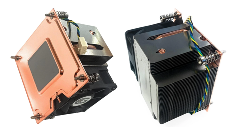
Figure 1 – A 2U Active Vapor Chamber 200W CPU Cooler with a Rated Speed of PWM 2600-8000RPM. Component Heat Boils an Internal Working Fluid to Enhance Thermal Transfer. Note the Flat Copper Vapor Chamber Base and Dense Fin Pitch to Uniformly Spread High Heat Loads. (Coolerguys) [1]

Some considerations when looking to cool components in these power ranges.  

One and Done – Air coolers are typically a one-time hardware cost with basic associated costs, e.g., attachment, TIM, power connection. These are well below the costs and maintenance associated with liquid cooling, e.g., pumps that may fail, coolant to flush or top off, cold plates, heat exchangers, tubing and connectors.

Catastrophic Risk – In a server environment a leaking liquid cooling system can take out an entire rack of hardware. An algae-clogged coolant line can reduce cooling performance, jeopardizing component performance and life.  Air cooling offers 100% liquid-free reliability.

Serviceability – A failed hot-pluggable high-performance cooling fan can easily be swapped out or cleaned for dust. Servicing liquid loops requires specialized tools and training, and longer system downtimes.
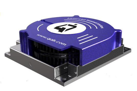
Figure 2 – A Heat Sink with High Performance, Top-Mounted Blower Designed for NVIDIA Jetson Thor Modules Provides 175W Cooling Capacity (Advanced Thermal Solutions, Inc.) [2]

Questions to Ask Before Choosing Air vs. Liquid

What is the deployment environment’s acoustic tolerance?

If the hardware sits in a windowless data center, segregated server room, or industrial telecom closet, definitely consider air cooling. The 70+ dBA noise of high RPM fans won’t matter there. If the component will be used in an office edge-server, a medical lab, or a workstation near human ears, choose a quieter cooling option, and certainly liquid cooling is one such choice.

What is the surrounding airflow topology and ducting design?

If a chassis allows for directed shrouding (baffles) to force intake air directly into a heat sink’s fin field, or if a blower can pull/push air through the sink from different sides, choose air. But if the PCB layout is cluttered, blocks airflow paths, or lacks a high-static pressure intake path, liquid cooling may be required to transport heat away via tubes.

Are you heading past the 250W–300W per-component barrier?

If you are cooling a 165W CPU or a 200W specialized accelerator, look into high-capacity air cooling systems to save on costs and eliminate leak risks. However, if the next-gen design will upgrade to a 400W+ AI processor, it would be more practical to design for liquid cooling early on. [3]
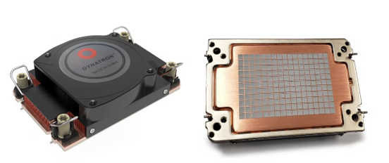
Figure 3 – A High-Capacity 1U Air Cooler with Vapor Chamber Base Designed for Intel Grand Rapids SP and Xeon 6 Processors. Its Fan Speeds Reach 8600 RPM and Cooling Performance Up to 330W. (Dynatron) [4]

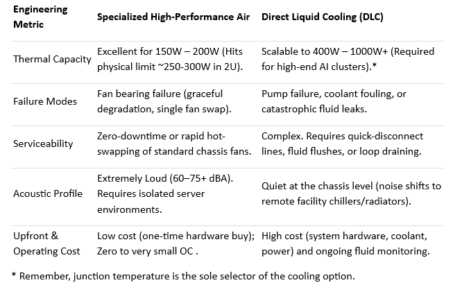
Let’s compare elements of high-capacity air cooling with alternative liquid cooling [5]:
References

  1. Coolerguys, https://www.newegg.com/p/3C6-00VJ-000E6
  2. Advanced Thermal Solutions, Inc., https://www.qats.com/Products/High-Capacity-Air-Cooling#QFLOW
  3. ServerMall, https://servermall.com/blog/air-or-liquid-server-cooling-which-to-choose-in-2026/
  4. Dynatron, https://www.dynatron.co/product-page/s7-4710
  5. Asperitas, https://www.asperitas.com/post/air-cooling-direct-liquid-cooling-and-single-phase-immersion

Hybrid Cooling: Air and Liquid Double-Team Heat in Data Centers

Much of the focus on data centers is on their very high power and cooling demands and the impact those demands have on local electrical grids and water supplies. Water is needed for thermally managing the hot-running processors, especially GPUs, at the heart of AI data center computing. Many other essential components also require cooling, but at lower levels, allowing them to be cooled using forced air.

This is why hybrid cooling, using both liquid and air methods, is an effective way to keep hot data center components within their operating temperature ranges. Hybrid cooling enables a more balanced, incremental approach to managing different types of heat loads efficiently. Liquid cooling handles concentrated heat loads, while airflow manages the remaining thermal load.

Figure 1 – Hybrid Air and Liquid Cooling Systems on a Data Center Server [2]

Forced air cools lower power components using heat sinks and air from fans and blowers. But traditional air cooling becomes inefficient as board and component densities climb, and power levels increase, justifying the need for high capacity air cooling that is not necessarily a larger fan of heat sink.  

Liquid cooling is provided by continuously circulating liquid coolant across the hot modules, drawing their heat away. While air cooling is provided by rows of fans, liquid cooling is a complex system of tubing and connectors, coolant distribution units (CDUs), cold plates, and coolants. [3]

Data Center Applications

Let’s look at hybrid cooling inside a typical server in an AI data center, where it can be one of thousands of servers running in tightly and precisely arranged rows of cabinets. Both air and liquid cooling play essential roles in thermally managing the many powered components.

Air Cooling

Server cases are explicitly designed to function as wind tunnels. Server airflow is generated by internal fans that create air pressure. Typically, these are high-static-pressure, counter-rotating fans that produce cooling airflow passing over and around motherboards and hot components. Fan pressure pushes heated air out of the server while drawing cool air in from outside. [4]

At the component level, air-cooling designs rely on conduction to move heat from a chip to a metal heat sink, followed by forced convection driven by high-static-pressure fans to carry the heat away.

Figure 2 – Fans Pull Air In and Across the Board. Warmed Air Exhausts Out the Back, e.g., into a Hot Aisle. [4]

Some commonly air-cooled components include:

  • Memory (DIMMs / DDR5): Cooled via linear front-to-back airflow channels passing across the motherboard.
  • Networking (NICs / SmartNICs / OCP 3.0 cards): Low-to-moderate-power PCIe or OCP networking modules.
  • Storage (NVMe / SSDs): Front-accessible U.2/U.3 or E1.S drives.
  • Power Supply Units (PSUs): Integrated hot-swap power supply modules equipped with their own independent, self-contained fans.
  • CPUs: Some lower-power CPUs can be air-cooled using low-profile fan-sinks or vapor-chamber heat sinks. [5]

In standard 1U and 2U multi-node enterprise server racks, CPUs and other components are almost always cooled passively using aluminum or copper block heat sinks that rely entirely on the high-RPM chassis fans located at the front of the server case.

Despite its broad applicability, air cooling is typically used for less than 20 kilowatts (kW) per rack in conventional designs, although it can reach 35 kW in exceptional cases. Anything beyond that typically requires liquid cooling. [6] Of course, the selection of a cooling system is governed by device junction temperature rather than total wattage.

Liquid Cooling

Liquid cooling systems circulate coolant through a network of tubing, absorbing heat from hot components, most notably high-power GPUs, many of which operate at 1,000 W.

Figure 3 – Liquid Cooling on a Data Center GPU. [7]

In data center servers, liquid cooling primarily targets ultra-high-heat-producing processors, specifically GPUs and CPUs, using direct-to-chip cold plates. In some advanced high-density 1U designs, liquid loops also extend coverage to adjacent high-power components.

Some commonly liquid-cooled components include:

  • GPUs / Accelerators: The core AI training and inference engines that generate the vast majority of server heat.
  • CPUs: Host processors that manage system instructions and data pipeline feeds to accelerators.
  • Network/AI Switches & Co-processors: Specialized fabric chips, such as NVSwitches, mounted on the board to link multiple processors at high speeds. [8]

Figure 4 – A Hybrid-Cooled 1U Rack Mount Server Chassis by Titan Rig includes 490W Cooling Capacity. A Powerfan Hub Bundle Provides Air-Cooling for Lower Power Components. [9]

Power of Two

Hybrid cars combine gas engines and electric motors to improve fuel efficiency. Similarly, hybrid cooling in data center servers combines air and liquid systems for greater thermal-management efficiency. Air cooling manages ambient and lower-density heat loads, typically up to 35 kW per server board. Liquid cooling targets high-intensity heat directly at the component level, such as CPUs and GPUs. Both systems operate simultaneously, reducing the thermal burden placed on either system alone.

Figure 5 – Liquid Cooling from ZutaCore Closely Neighbors an Air Cooling Heat Sink on a Server Board. [3]

Data center cooling isn’t only about installing fans and circulating coolant. Strategic design combined with optimization is crucial for ensuring that data center infrastructure and components operate at their best. This approach not only prevents devices from overheating but also maximizes the efficient use of data center resources, including power and cooling systems.

While this post focuses on component cooling within servers, data centers also have other thermal-management systems. In particular, their HVAC systems deliver chilled airflow to targeted areas within the facility. By optimizing airflow through vents and barriers, data centers can minimize areas of stagnant air. Configuring server racks in alternating hot- and cold-aisle rows maximizes efficiency by ensuring that cooled air is delivered where it is needed most while preventing hot and cold air from mixing.

References

  1. Top Image https://www.gigabyte.com/Enterprise/GPU-Server/G262-ZL0-rev-G00
  2. Tech Stories, https://www.techstories.co/liquid-cooling-leak-destroys-millions-of-dollars-in-gpus/
  3. Chatsworth, https://www.chatsworth.com/en-us/resources/blogs/2026/what-is-hybrid-cooling-a-smarter-approach-to-data-center-thermal-design/
  4. EziBlank, https://eziblank.com/blog/2022/11/29/how-airflow-works-inside-of-a-server/
  5. Cooltron, https://www.cooltron.com/news/thermal-engineer’s-guide-to-choosing-ai-server-cooling-fans-2078026334647910402
  6. Digital Reality, https://www.digitalrealty.com/resources/blog/future-of-data-center-cooling
  7. Jetcool, https://jetcool.com/post/what-is-direct-liquid-cooling-for-ai-data-centers/
  8. Solidigm, https://www.solidigm.com/products/technology/liquid-cooling-basics.html
  9. Titan Rig, https://www.titanrig.com/1u-liquid-cooled-rack-mount-server-chassis-with-490w-cooling-capacity-xpx-pro-cpu-water-block-es-guardian-powerfan-hub-bundle.html

Accurate Instruments are Essential When Measuring for Thermal Management Solutions

By collecting and analyzing more relevant measurement data, electronic cooling systems can be designed for improved performance, reliability, and cost. It’s essential these measurements be as accurate as possible. Critical data points include component temperature, air temperature, air flow rate, and often air pressure. Accuracy becomes even more important when performing accelerated testing as seen in this post.

Research-grade instruments and specialized sensors, properly calibrated and operated, can measure chip temperatures and surrounding elements, such as local airflow. Separate instruments can be used to quantify specific conditions, but more real-use data is obtained when all points are collected simultaneously. Taken over a range of time and conditions, simultaneous measurements provide more accurate, actionable information. They also reduce the cost and set-up time for multiple studies.

Fig 1 – Input Ports for a Laboratory Instrument that Simultaneously Measures Air Velocity, Temperature and Pressure. [ATS]
Fig 2 – High-quality Thermal Data Reduces Uncertainties in Cooling Solutions than Calculated Data. [ATS]

Accelerated Product Reliability Testing

Reliability testing at different temperatures and conditions is commonly performed to identify expected product life. When an electronic system is running, it continuously experiences temperature and power cycling. These fluctuations are typically normal, but should be factored into a comprehensive thermal profile study.

It’s not practical to wait years to see if a component fails. Accelerated life testing provides faster predictions. A commonly used predictive tool is the Arrhenius model shown below.

Accelerated life testing using the Arrhenius model is a method for predicting how long a product will last under normal conditions by running it at elevated temperatures for a shorter time. The temperature increase speeds up the same failure processes that would eventually occur in the field—compressing years of life into weeks of testing.

Accelerated life testing Arrhenius calculators can help estimate field lifetime, test duration, acceleration factors, activation energy, and field failure rates. These tools are useful when real-time qualification can’t be done. This is typical with electronic components and devices that need fast market introduction. One such calculator is found here: Accelerated Life Test Arrhenius Calculator. [1]

The Arrhenius Model handles pure thermal stress, while the Eyring Model includes temperature plus other active forces like humidity or voltage. [1,2]

Highly Accurate Thermal Instruments

Besides its design, a thermal instrument’s construction and calibration should be high quality, and not a source of more errors. Accurate, research-grade instruments are essential for valid engineering practices. Without them, reliability predictions for a new product are actually less reliable themselves.

Fig 3 – Candlestick Sensors are Thin Profile (0.5 mm) with a Small Base (9.5 mm dia) for Collecting Air Temperature and Velocity Data at Single or Multiple Locations. [ATS]
Fig 4 – Here, Air Temperature and Velocity Measurements are Taken Every Second by an eATVS-8 Instrument. stageVIEW Software Provides a Wide Range of Data Collection Choices. [ATS]


Here are some of the ATS instruments available for temperature and velocity measurement and providing the highest-quality thermal reliability test results.

Conclusion

Temperature has a significant effect on reaction rate and the subsequent reliability prediction. Small errors in temperature and airflow measurements can significantly impact reliability predictions. Such errors typically occur in the measurement process or from using inaccurate instruments.

If thermal data is inaccurate, outcomes can include over-designed systems, cost overruns, and products not shipping.

Laboratory-quality thermal instruments can reduce or eliminate measurement and calculation mistakes, leading to higher quality, faster to market and ultimately lower cost products. Just as important, collected data needs to be correctly interpreted. Expert thermal engineers can do just that with data provided or that they obtain themselves.

More information on these topics can be seen at these ATS videos:

How to Properly Measure Air Velocity in Electronic Systems [Link] [3]

How to Perform and Understand Temperature Measurement within Electronic Systems [Link] [4]

stageVIEW Software Demo [Link] [5]

References

  1. Firgelli Automations, https://www.firgelliauto.com/blogs/calculators/accelerated-life-test-arrhenius-calculator
  2. NIST, https://www.itl.nist.gov/div898/handbook/apr/section1/apr152.htm
  3. Advanced Thermal Solutions, Inc., https://vimeo.com/reviews/a4e9a72d-d228-489f-8edb-a98e440a8ef1/videos/113427506
  4. Advanced Thermal Solutions, Inc., https://vimeo.com/reviews/63784f1b-a32d-4f90-86b1-5bf362715619/videos/113432468
  5. Advanced Thermal Solutions, Inc., https://www.youtube.com/watch?v=Lx5NlAI5TuM

The Importance of Thermal Management

Excess heat has affected electronic devices since their earliest days, becoming more critical with the advent of integrated circuits. Today, excess heat impacts the reliability, performance, and lifespan of devices and circuits across all applications. Common impacts of excess heat in electronics are:

Overheating: This can cause sudden shutdowns or failures. Elevated temperatures damage internal components, leading to permanent failure and potential safety risks—especially in high-power systems such as batteries and automotive electronics.

Lower performance: Overheating devices often throttle to reduce heat, and signal integrity may degrade, resulting in reduced performance. Maintaining operation within the designated temperature range lowers electrical resistance and power consumption while improving energy efficiency.

Shorter lifespans: High temperatures cause differential material expansion and deformation, damaging component structures and internal connections.

Thermal issues can also lead to field recalls and warranty claims. Dense PCB layouts may introduce thermal coupling between components, compounding heat-related risks.

Best practice is to engage thermal management specialists early. Effective thermal management controls and dissipates heat to maintain safe operating temperatures. Cooling solutions vary widely, but viable approaches exist for nearly every application.

Applying Professional Thermal Design

Effective cooling solutions require rigorous analysis at the concept stage, development, and testing. The thermal design process includes analytical modeling, experimental validation, and computational simulation across the full packaging domain—components, PCBs, shelves, chassis, and system enclosures.

Figure 1. CFD Simulation of Forced Airflow Across Areas of a Populated PCB.

Robust thermal design leverages both experimental and computational methods, using lab instrumentation and CFD tools such as FloTHERM, CFdesign, and Icepak, among other commercially available tools.

Empirical methods may include airflow or liquid testing, with measurements of velocity, temperature, and pressure, along with thermography using IR or liquid crystal techniques.

A disciplined, methodical approach consistently delivers strong results across diverse cooling challenges. OEMs can often avoid costly redesigns or recalls through expert thermal review, whether on-demand or via ongoing engineering partnerships. Subscription-based thermal services further accelerate validation and integrate thermal considerations earlier in development. More on these below.

Following are examples of carefully applied cooling design methodology.

Dual-Environment Thermal Analysis of a Sealed Offshore Electronics Enclosure

After detailed analytical modeling to envelop the solutions, CFD analysis was performed on a sealed offshore aquaculture enclosure operating in two passive environments: submerged seawater at 30°C and outdoor air at 40°C. The objective was to determine whether passive cooling could maintain component temperatures below 60°C.

Figure 2. (left) Outer Enclosure Temperature Contours. (center) An Internal Aluminum Sled to Transfer Component Heat to the Outer Enclosure. (right) Velocity Vectors Indicate the Slow Motion of the Internal Air.

The analysis showed the passive design was insufficient for the outdoor air case. Key limitations included weak natural convection and poor internal conduction to the enclosure walls. Hot spot spreading resistance significantly contributed to overall temperature rise.

Addressing the air case would also resolve the submerged case. Recommended improvements:

  1. Increase external surface area with fins or a bonded heat sink
  2. Improve internal conduction and reduce interface resistance
  3. Integrate heat pipes or vapor chambers to reduce spreading resistance

Multi-Cold-Plate Liquid Cooling System Design and Optimization

An EV battery manufacturer developed a 4 kW liquid cooling system with four cold plates integrated into a loop including a heat exchanger, DC-DC converter, and onboard charger. The design required balancing thermal performance, manufacturability, and flow distribution.

Figure 3. Four Cold Plates Receive Chilled Coolant from a Heat Exchanger as Part of a Liquid Loop that Included a DC-DC Converter and On-board Charger.

ATS combined analytical modeling with CFD to optimize cold plate geometry and system flow. Key parameters included tube routing, thermal resistance, and pressure drop.

Figure 4. CFD Simulation of a Revised Cold Plate with 10 Tube Passes and 9 Tube Bends.

A 10-pass serpentine tube design maximized heat transfer while maintaining acceptable pressure drop and manufacturability. Additional improvements included optimized tube diameters and balanced manifold routing.

The study demonstrated that effective kilowatt-scale liquid cooling requires coordinated optimization of geometry, pressure drop, and flow distribution. General findings:

  1. Balanced conduction and convection are critical
  2. Targeted passive changes can yield significant gains
  3. System-level optimization outperforms isolated fixes

CFD-Driven Thermal De-Risking of a Ruggedized Rack System

A baseline-to-optimization CFD study was conducted on a sealed 241 W ruggedized rack system with a 55°C ambient limit. The goal was to identify thermal violations and develop a reliable cooling strategy.

Figure 5. CFD Baseline Model and Surface Temperature Contours of a Ruggedized Rack System.

Through iterative CFD-driven design changes, ATS improved airflow efficiency, heat sink performance, and heat routing. Final modifications included revised heat pipe routing, heat sink replacement, fan reconfiguration, and removal of airflow obstructions. All components achieved thermal compliance.

Figure 6. Surface Temperature Contours of the System’s (left) Original Pin-Fin Heat Sink, and Its Replacement (right) maxiFLOW Heat Sink.

The study showed that sealed systems require holistic optimization across airflow, heat flow routing, fan placement, and heat sink design. General findings:

  1. Analytical modeling identified areas requiring attention and possible solutions
  2. Baseline CFD validated the findings in ‘1’ and identified thermal risks before failure
  3. Heat sink upgrades alone are insufficient without airflow optimization
  4. Iterative CFD enables targeted, low-risk refinement
  5. Final designs improve both compliance and thermal margin

Thermal Optimization of a Passive Aluminum Enclosure

ATS evaluated a sealed passive aluminum enclosure dissipating 75.8 W at 25°C ambient. CFD and parametric analysis identified key thermal constraints and guided optimization.

Figure 7. (left) Distribution of Enclosure Components, (right) Enclosure Baseline Thermal Distribution CFD.

Using 3D CFD with conjugate heat transfer, ATS modeled conduction and natural convection. Results showed that achieving target performance required coordinated improvements across both mechanisms.

Enhancements included improved thermal interface materials, better heat spreading, optimized fin geometry, reduced obstructions, and added vent gaps to enhance natural convection pathways.

Figure 8. The Enclosure Thermal Optimization Included Adding Cross-Cut Venting Gaps to Optimize Natural Convection.

Passive cooling performance is governed by the interaction of internal conduction and external convection. Key limitations included interface resistance and restricted airflow, with diminishing returns from geometry-only changes. Findings:

  1. Balanced conduction and convection are essential
  2. Targeted passive improvements deliver measurable gains
  3. System-level optimization is more effective than isolated changes

Conclusion

Modern electronics—including AI hardware—generate substantial heat loads, making thermal management a first-order design constraint. Large-scale systems such as data centers incorporate cooling from the outset, but thermal design is equally critical at smaller scales.

Figure 9. ATS Thermal Engineers Use Thermochromic Liquid Crystals to Reveal Hot Spots in Electronic Devices. See a Demonstration Video: https://www.youtube.com/watch?v=peewxRlNVqg

Every application presents unique challenges, and thousands of new devices each year require tailored cooling solutions.

When clients have excess heat issues, ATS engineers work closely with them to deliver cost-optimized, practical thermal and mechanical solutions that align with real-world schedules. The objective is consistent: deliver the right solution the first time.

For OEMs and others with continuing needs for thermal engineering, ATS now provides a subscription service. This comes with tiered support levels, ranging from periodic consultation to embedded engineering support within development teams. Contact ATS for more information on the thermal engineering subscription service.

Figure 10. ATS Thermal Engineering Consulting Tiers Match a Manufacturer’s Ongoing Needs.

To see more details on the above cooling applications, and others, see the Advanced Thermal Solutions, Inc. website, https://www.qats.com/Consulting

Cooling Hot Electronics with Cold Plates

Cold plates have been used for thermal management since the Apollo moon missions in the 1960s. Today, they serve a critical role in cooling high-performance electronics across many industries.

Power electronic devices generate significant heat, and if their chips exceed safe temperature limits, system reliability and longevity are compromised. Effective thermal management is essential, as lowering a chip’s junction temperature by just 10°C can double its operational life.

Cold plates offer highly efficient, localized cooling by transferring heat from hot components—such as power semiconductors—into a liquid coolant flowing through the plate. The heated liquid then moves to a remote heat exchanger, where it cools before recirculating back to the cold plate.

Compared to forced-air cooling, cold plates deliver superior thermal performance. They are typically smaller, quieter, and lighter than fan-based systems, making them an attractive solution in compact or noise-sensitive environments.

Most cold plates consist of thin-walled aluminum or copper blocks with internal channels or tubing for coolant flow. As liquid moves through the plate, it absorbs heat from the attached components and carries it away for external dissipation. Modern designs often use mini-channels instead of traditional tubing. These intricate internal pathways maximize surface contact with the coolant, improving heat transfer and cooling efficiency.

Figure 1 – Cold Plates are Part of a Liquid Cooling Loop that Includes a Pump for Fluid Circulation and a Heat Exchanger to Remove Heat from the Flowing Coolant. [ATS]

More advanced cold plates feature mini-channels in place of tubing. These designs can better match applications and more efficiently transfer heat into the coolant.

Figure 2 – A Cold Plate with Internal Mini-Channels Provides a High Rate of Thermal Transfer to Remove More Component Heat. [ATS]

Tubed Cold Plates Cool Hot Electronics

Embedded tube designs are the simplest cold plates. They feature a stainless steel or copper tube coiled and set into grooves inside a metal base plate. The tubes can be routed in different pathways to optimize thermal transfer performance. The flowing coolant moves heat from the component, away from the cold plate and over to a heat exchanger where it is cooled before being pumped back to the plate.

Figure 3 – A Tubed Cold Plate Can Consist of Copper or Stainless-Steel Tubing Pressed or Embedded in a Metal Plate. [ATS]

These tubed cold plates are cost-effective solutions for low- to moderate-power applications and are ideal for use in automotive, instrumentation, and UPS systems. ATS offers models ranging from 57–914 mm in length and 57–198 mm in width, with push-to-connect fittings for easy installation.

A variation of this design features thermally conductive epoxy completely covering the tubing and flush with the plate’s surface. This not only improves thermal contact but also provides environmental protection by sealing the tube within the plate.

Figure 4 – A Cold Plate’s Tubing Can be Buried and Covered with a Thermally Conductive Epoxy Layer. [1]

Custom Cold Plates Provide Best Cooling Solutions

For more demanding applications—such as cooling BGAs, LEDs, or high-power modules—custom cold plates offer the best performance. These can include embedded tubing or submerged internal fins, which increase surface area and create turbulence to enhance heat transfer.

Figure 5. Custom Liquid Cold Plate with Inlaid Copper Tubing Provides Heat Transfer Away from Hot Electronics [2]

One example uses tightly spaced aluminum pin fins to generate turbulence with minimal pressure drop, achieving high thermal performance while keeping the plate compact. Another design incorporates internal turbulators tailored for IGBT modules, further improving coolant flow and heat dissipation.

ATS designs and manufactures custom cold plates in collaboration with customers or based on in-house thermal analysis. These designs can include complex internal geometries such as microchannels or gyroid lattices, like the 3D-printed cold plate created for race car IGBT cooling—an approach that improves flow guidance while reducing weight.

Figure 6. Close-spaced Pin Fins with Complex Geometry Create Turbulence with Low Flow Rate Values Inside Submerged Fin Cold Plates. [3]
Figure 7. A Custom IGBT-Cooling Cold Plate Features Internal Turbulators to Optimize Coolant Turbulence and Heat Transfer. [4]

ATS constructs cold plates to customer designs and those developed in partnership with our own thermal engineers. ATS coolant-based cold plates can include internal tubing and microchannels in closed loop systems.

Figure 8. Dual-Sided Cold Plates Cool Components on Both of Their Mounting Sides. [ATS]

Dual-sided high-flow cold plates provide equal cooling performance for components mounted on both sides of the plate, increasing efficiency, space savings and economy. The cold plates can be used with coolant flow rates up to 4 gal/min, and provide thermal resistance as low as 0.0021°C/W. [5]

Figure 9 – This 3D-Printed Metal Cold Plate Cools IGBTs on a Race Car. It Features a Gyroid Lattice That Guides Internal Coolant Flow While Reducing the Overall Weight [6]

DIY Cold Plates Optimize Component Cooling

ATS also offers DIY (do it yourself) cold plates with modular dimensions and pre-defined drill zones. Engineers can customize mounting locations to match specific components. Once the ideal configuration is determined, ATS can mass-produce the cold plate to match exact specifications.

Figure 10 – Do It Yourself Cold Plates from ATS Feature Drill Zones for Precision Matching to Heat Sources, and No Drill Zones to Protect Internal Coolant Flow Channels. [ATS]

The Complete Liquid Cooling Loop

Cold plates are just one part of a complete liquid cooling system. As electronics demand more efficient cooling, liquid-based systems are increasingly replacing air-based solutions. A functional loop includes a pump, reservoir, and heat exchanger to remove heat from the circulating fluid.

Figure 11 – A Liquid Cooling Loop Featuring Cold Plates. This is Implemented in Avionics on F-16 Fighting Falcon Jets. [7]

These systems are becoming more cost-effective and safer, making liquid cooling viable for a broader range of applications. Cold plates serve as a critical stage in these loops, offering simplicity, versatility, and high thermal performance.

Plug and Play Liquid Loops

For streamlined implementation, ATS offers the Industrial Cooling Distribution Module™ (iCDM™)—a fully integrated liquid cooling loop in one compact, portable unit. It includes the pump, heat exchanger, reservoir, precision controls, and monitoring displays, eliminating the need to purchase and configure components separately.

Figure 12 – The New Industrial Cooling Distribution Module Contains the Pump, Heat Exchanger, Reservoir and Controls for Managing Coolants in Liquid Cooling Loops. [ATS]

The iCDM connects directly to cold plates or chassis-based cooling systems. It supports models with cooling capacities of 10 kW and 20 kW, each holding up to 2 liters of coolant. The system is compatible with a wide range of wetted materials, allowing flexible deployment across industries. A next-generation iCDM, available soon, is fully automated, with significantly increased cooling capacities up to 1.4MW.

Conclusion

Cold plates can provide essential electronics cooling because of their design versatility and the power of liquid cooling. AI chip cooling cold plates will soon be available for this growing and demanding arena.

ATS engineers are experts in matching thermal solutions to system needs, offering a wide portfolio that includes cold plates, vapor chambers, coolant chillers, and complete liquid loop systems. Whether liquid cooling is the best solution depends on the specific application, and ATS provides detailed analysis to help customers make informed decisions.

References

  1. Wakefield Thermal, http://www.wakefield-vette.com/products/liquid-cooling/liquid-cold-plates/standard-liquid-cold-plates.aspx
  2. Baknor, https://www.baknorthermal.com/liquid-cold-plates-various-channel-options/
  3. COOLTECH, http://www.cooltech.it/products/liquid-cold-plates/
  4. Boyd Corp., https://www.boydcorp.com/thermal/liquid-cooling-systems/liquid-cold-plates.html
  5. ATS, https://www.qats.com/Products/Liquid-Cooling/Dual-Sided-Cold-Plates
  6. nTop, https://www.ntop.com/resources/case-studies/cold-plate-automotive-power-electronics/
  7. ThermOmegaTech, https://www.tot-ad.com/avionics-cooling/