
Tag Archives: heat sink

Use High-Capacity Air Coolers in Place of Liquid Cooling for 200W+ Components

When server components reach 150W and higher TDP (total dissipated power), hardware engineers tend to look to cool them with liquid. These will provide effective thermal relief, if applied properly, but liquid cooling brings more concerns into the server chassis. These include pumps that can fail, seals that can leak, liquids that can foul, and a leap in the system TCO (total cost of ownership). But liquid cooling may not be needed at these power levels.

No matter what thermal management system you choose, the key criterion for component cooling is the internal junction temperature (Tj), short for junction temperature. This is the hottest temperature of a semiconductor device’s silicon die during operation. While there is correlation between junction temperature and power use, these vary by types of devices. Selection of a cooling system solely to power use is not necessarily going to manage the heat output from its junction temperature. However, for the sake of clarity and conveyance of cooling options, here we refer to power as the beacon for cooling option.

There is a range of high-capacity, non-liquid solutions available to effectively cool components running up to 200W. These cooler can even be deployed in tight headroom 1U and 2U chassis. They combine high density fins with high-output, high-power fans to cool components including AI processors, CPUs, FPGAs and GPUs.
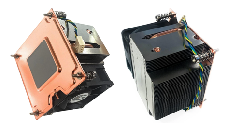
Figure 1 – A 2U Active Vapor Chamber 200W CPU Cooler with a Rated Speed of PWM 2600-8000RPM. Component Heat Boils an Internal Working Fluid to Enhance Thermal Transfer. Note the Flat Copper Vapor Chamber Base and Dense Fin Pitch to Uniformly Spread High Heat Loads. (Coolerguys) [1]

Some considerations when looking to cool components in these power ranges.  

One and Done – Air coolers are typically a one-time hardware cost with basic associated costs, e.g., attachment, TIM, power connection. These are well below the costs and maintenance associated with liquid cooling, e.g., pumps that may fail, coolant to flush or top off, cold plates, heat exchangers, tubing and connectors.

Catastrophic Risk – In a server environment a leaking liquid cooling system can take out an entire rack of hardware. An algae-clogged coolant line can reduce cooling performance, jeopardizing component performance and life.  Air cooling offers 100% liquid-free reliability.

Serviceability – A failed hot-pluggable high-performance cooling fan can easily be swapped out or cleaned for dust. Servicing liquid loops requires specialized tools and training, and longer system downtimes.
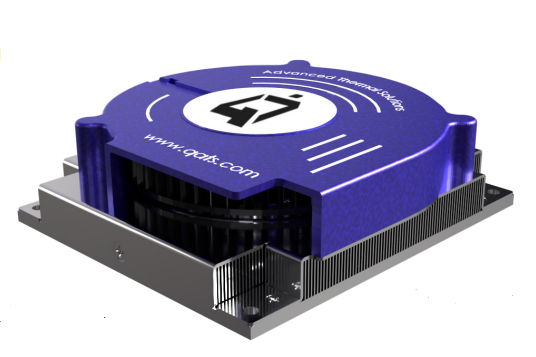
Figure 2 – A Heat Sink with High Performance, Top-Mounted Blower Designed for NVIDIA Jetson Thor Modules Provides 175W Cooling Capacity (Advanced Thermal Solutions, Inc.) [2]

Questions to Ask Before Choosing Air vs. Liquid

What is the deployment environment’s acoustic tolerance?

If the hardware sits in a windowless data center, segregated server room, or industrial telecom closet, definitely consider air cooling. The 70+ dBA noise of high RPM fans won’t matter there. If the component will be used in an office edge-server, a medical lab, or a workstation near human ears, choose a quieter cooling option, and certainly liquid cooling is one such choice.

What is the surrounding airflow topology and ducting design?

If a chassis allows for directed shrouding (baffles) to force intake air directly into a heat sink’s fin field, or if a blower can pull/push air through the sink from different sides, choose air. But if the PCB layout is cluttered, blocks airflow paths, or lacks a high-static pressure intake path, liquid cooling may be required to transport heat away via tubes.

Are you heading past the 250W–300W per-component barrier?

If you are cooling a 165W CPU or a 200W specialized accelerator, look into high-capacity air cooling systems to save on costs and eliminate leak risks. However, if the next-gen design will upgrade to a 400W+ AI processor, it would be more practical to design for liquid cooling early on. [3]
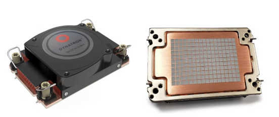
Figure 3 – A High-Capacity 1U Air Cooler with Vapor Chamber Base Designed for Intel Grand Rapids SP and Xeon 6 Processors. Its Fan Speeds Reach 8600 RPM and Cooling Performance Up to 330W. (Dynatron) [4]

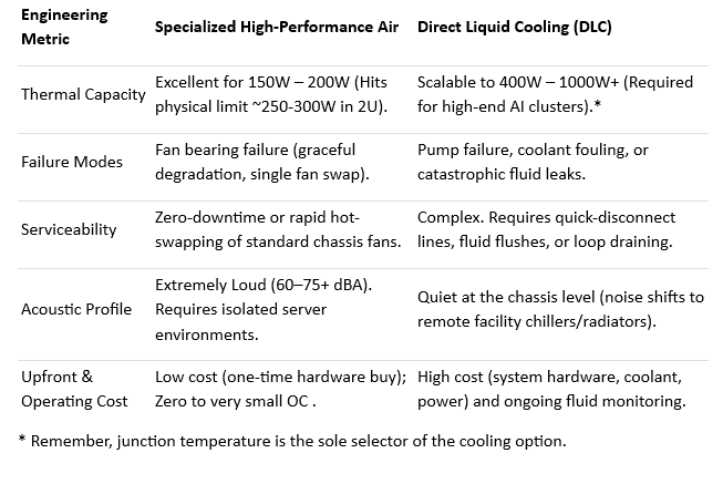
Let’s compare elements of high-capacity air cooling with alternative liquid cooling [5]:
References

  1. Coolerguys, https://www.newegg.com/p/3C6-00VJ-000E6
  2. Advanced Thermal Solutions, Inc., https://www.qats.com/Products/High-Capacity-Air-Cooling#QFLOW
  3. ServerMall, https://servermall.com/blog/air-or-liquid-server-cooling-which-to-choose-in-2026/
  4. Dynatron, https://www.dynatron.co/product-page/s7-4710
  5. Asperitas, https://www.asperitas.com/post/air-cooling-direct-liquid-cooling-and-single-phase-immersion

Extruded, Skived or Zipper Fin Heat Sinks

Which is Right for Your Design?

Compare extruded, skived, and zipper fin heat sinks to find the best thermal management solution for electronics, telecom, AI, and power applications.

As power densities continue to increase in electronics, thermal management has become a critical design consideration. Selecting the right heat sink technology can significantly impact system performance, reliability, size, and cost.

Let’s look at the differences between these heat sink technologies and provide guidance on where each solution performs best.

Extruded Heat Sinks

Extruded heat sinks are manufactured by forcing heated aluminum through a shaped die, creating a continuous profile that can be cut to desired lengths. This process produces an integral structure where the base and fins are formed from a single piece of material. [1]

Advantages

  • Lowest manufacturing cost for medium-to-high volume production
  • Excellent mechanical strength due to one-piece construction
  • Wide availability and short lead times
  • Lightweight and corrosion-resistant
  • Suitable for many general-purpose cooling applications

Fig 1 – Extruded Aluminum Heat Sinks are Produced in Continuous Profiles to be Cut to Desired Lengths. [2,3]

Limitations

  • Fin height and fin density are limited by extrusion tooling constraints
  • Typically manufactured from aluminum alloys only
  • Lower thermal performance compared to advanced fin technologies
  • Less effective in high-power or space-constrained designs

Best Applications for Extruded Heat Sinks include:

  • Industrial controls
  • Power supplies
  • LED lighting systems
  • Telecommunications equipment
  • Consumer electronics
  • Moderate-power electronics with natural or forced-air cooling

When cost, simplicity, and manufacturability are primary concerns, extruded heat sinks often provide the best overall value.

Skived Fin Heat Sinks

Skived heat sinks are produced by slicing thin layers of material from a solid metal block and bending them upward to form fins. Because the fins remain attached to the base material, the resulting structure maintains excellent thermal conductivity.

Both aluminum and copper can be used, with copper skived heat sinks offering particularly high thermal performance. [4,5]

Advantages

  • Higher fin density than extrusion
  • Taller, thinner fins improve heat transfer
  • No thermal interface between fins and base
  • Excellent thermal conductivity
  • Can be manufactured from copper for demanding applications

Fig 2 –  Skived Heat Sinks are Produced by Slicing Thin Layers from a Solid Metal Block and Bending Them to Form Fins. [6,7]

Limitations

  • Higher manufacturing cost than extrusions
  • More complex fabrication process
  • Practical limits on fin geometry still exist
  • Heavier when copper is used

Applications that Skived heat sinks excel in:

  • High-performance computing
  • CPUs and GPUs
  • Networking equipment
  • Power conversion systems
  • Medical electronics
  • Aerospace and defense electronics

Designers often select skived heat sinks when thermal performance requirements exceed the capabilities of traditional extrusions but a bonded-fin assembly is unnecessary.

Zipper Fin Heat Sinks

Zipper fin heat sinks use individually stamped metal fins that are mechanically interlocked into grooves in a base plate. The fins resemble the teeth of a zipper, giving the technology its name. This manufacturing approach allows extremely high fin densities and flexible fin geometries that are difficult or impossible to achieve through extrusion or skiving. [8]

Advantages

  • Extremely high fin density
  • Excellent airflow utilization
  • Can be integrated with heat pipes
  • Flexible fin shapes and configurations
  • Available in aluminum, copper, or mixed-material designs
  • Ideal for forced-air cooling applications
  • Supports large cooling surface areas in compact footprints

Figure 3 – Zipper Fin Heat Sinks use Individually Stamped Metal Fins Interlocked into a Base Plate, Shown Here with Integral Heat Pipes. [9,10]

Limitations

  • Higher manufacturing complexity
  • More expensive than standard extrusions
  • Thermal resistance at fin-to-base interfaces can be slightly higher than monolithic designs
  • Typically optimized for systems with active airflow

Zipper fin heat sinks are commonly used in:

  • Data center servers
  • AI and HPC systems
  • Telecom infrastructure
  • Base stations
  • Enterprise networking equipment
  • High-power FPGA and ASIC applications

Whenever maximum cooling performance is required in a constrained space with forced airflow available, zipper fin heat sinks are often the preferred solution.

Key Considerations and Performances of Heat Sink Types

The optimal choice depends on thermal requirements, available space, airflow conditions, and budget. [11,12]

Choose an Extruded heat sink when:

  • Cost is a primary concern
  • Thermal loads are moderate
  • Standard profiles meet design requirements
  • Production volumes are high

Choose a Skived heat sink when:

  • Higher thermal performance is needed
  • Increased fin density is beneficial
  • Copper construction is desirable
  • Space is limited but airflow may be moderate

Choose a Zipper Fin heat sink when:

  • Maximum cooling performance is required
  • Forced airflow is available
  • Fin density must be maximized
  • Thermal constraints are severe

Summary

No single heat sink technology can provide every electronic cooling solution. Extruded heat sinks remain the most economical solution for many designs, while skived heat sinks offer improved thermal performance through higher fin densities and superior material options. For the most demanding thermal challenges, zipper fin heat sinks provide exceptional cooling capability and design flexibility.

Ultimately, the ideal heat sink is one that satisfies thermal requirements while meeting mechanical, manufacturing, and economic objectives. By carefully evaluating airflow, thermal load, space constraints, materials, and cost, engineers can select the most effective thermal management solution for their specific application.

References

  1. Eaton, https://www.eaton.com/us/en-us/catalog/thermal-management-solutions/aluminum-extrusion-profiles.html
  2. Rapid Direct, https://www.youtube.com/watch?v=nIcYV1lDs2w
  3. Davantech, https://www.davantech.com/milling-customized-extruded-aluminum-heatsinks-precision-manufacturing-for-efficient-heat-dissipation/
  4. KenFa Tech, https://www.kenfatech.com/skived-vs-extruded-heat-sink/
  5. Kimsen, https://kimsenglobal.com/skived-fin-heat-sink-technical-deep-dive-for-engineers/
  6. Wekiko-Bythermal, https://www.youtube.com/shorts/RzM_fObq4w0
  7. Heatell, https://www.heatell.com/skived-fin-heat-sink/?utm_source=chatgpt.com
  8. Eaton, https://www.eaton.com/us/en-us/products/thermal-management-solutions/materials-finishes/zipper-tech-overview.html
  9. Gito Machine, https://www.youtube.com/shorts/_JJR477bHjQ
  10. Advanced Thermal Solutions, Inc., https://www.qats.com/Heat-Sinks/Zipper-Fin
  11. Boyd, https://info.boydcorp.com/hubfs/Resources/Resource-Center/Boyd-Guide-to-Heat-Sink-Fabrications-2020-Technical-Paper.pdf
  12. KingKa Tech, https://www.kingkatech.com/Skived-Vs-Extruded-Heat-Sinks-What-Are-The-Key-Differences-id48217376.html

Case Study: LED Solution for Outdoor Canopy Array

Advanced Thermal Solutions, Inc. (ATS) was approached by a company interested in a new design for an outdoor LED unit that would be installed in gas station canopies. The original unit was bolted together and contained a molded plastic shroud that held the LED array, the PCB, and an extruded aluminum heat sink.

ATS engineers designed an aesthetically pleasing alternative that utilized natural convection cooling, while increasing the number of the LEDs in the array and its power. The engineers met the customer’s budget and thermal performance requirements.

• Challenge: Create an outdoor canopy device that would increase the number of LED in the array, increase power to maximum of 120 watts, and increase lumens, while cooling the device through natural convection.

• Chip/Component: The device had to hold an LED array and the PCB that powered it.

• Analysis: Analytical modeling and CFD simulations determined the optimal fin efficiency to allow air through the device and across the heat sink, the spreading resistance. The weight of the device was also considered, as it would be outside above customers.

• Solution: An aesthetically-pleasing, one-piece, casted unit with built-in electronics box for LED array and PCB was created. There was one inch of headroom between the heat sink and the canopy to allow for heat dissipation and the casting would allow heat transfer as well as allow air to flow through the system.

• Net Result: The customer was able to add LEDs to the array and increase power. The new unit also simplified the manufacturing process and cut manufacturing costs.

For more information about Advanced Thermal Solutions, Inc. thermal management consulting and design services, visit www.qats.com or contact ATS at 781.769.2800 or [email protected].

Case Study: Thermal Management in Harvard Medical School Tissue Analysis Instrumentation

Designers of today’s highly advanced medical diagnostic equipment must overcome many of the same thermal challenges common to telecommunications, industrial and information technology electronics.

In addition, medical diagnostic devices present unique design issues and boundary conditions that factor into thermal solutions. These include isothermal and cyclic temperature demands, precise test repeatability, and maintaining the patient’s safety and comfort.

These kinds of issues were presented by Harvard Medical School to the experts at Advanced Thermal Solutions, Inc. (ATS) when it needed a cooling solution for the diagnostic equipment it was relying on for the analysis and observation of human tissue samples in a controlled laboratory setting. This was the school’s Frozen Tissue Microarrayer System.

ATS engineers had to provide thermal solutions to meet a range of design goals:

• Provide long-term temperature control for tissue samples embedded in an optimum cutting temperature fluid.
• Create a cooling system to maintain tissue samples below -70°C for six hours.
• Ensure operator visibility of the samples.
• Eliminate humidity and frost within the system to prevent sample contamination.

ATS Cooling Solutions

ATS engineers developed highly effective thermal solutions to meet all the design requirements of the diagnostic equipment. A reservoir in the device holds the liquid cooling medium and tissue samples are loaded through an opening at the top. Through a duct, cool air is circulated over the top of the samples to maintain temperature and humidity requirements.

As seen in Fig. 1 (below), the diagnostic system consisted of:

• Frozen tissue coring machine (on the right in the photo)
• Tissue sample loading area at the top of the cooling system (seen on the left)
• Duct system (on both sides of system) to circulate cool air
• Ice/alcohol reservoir at the system’s bottom to contain the cooling medium

Harvard Case Study

Figure 1. Prototype system created by ATS engineers for Harvard Medical School laboratory. (Advanced Thermal Solutions, Inc.)

Conduction Cooling Design

In operation, tissue samples are loaded into removable aluminum cassettes that fit tightly into a metal receiver (top left, Figure 2). The receiver contacts the cassette on five sides which allows for cooling of the samples by conduction. The receiver is lowered into a reservoir containing a slurry of dry ice and ethyl alcohol. Here the receiver is maintained at a constant temperature until the dry ice evaporates. The reservoir is double-walled and insulated to extend the evaporation time of the dry ice.

The receiver also features integral fins that increase surface area for drawing heat downward from the base of the cassettes into the icy slurry (bottom left, Figure 2). These fins are based on the same ATS heat sink design principles used in the company’s high performance maxiFLOW™ heat sinks.

Using analytical modeling, ATS engineers determined that 10 fins were the optimal number for cooling the cassette receiver and its contents. CFD simulations also showed that the 10-fin concept resulted in an optimal design. The engineers validated their analytical and CFD results through empirical testing. It was determined that extending 10 fins into the slurry provided the cooling performance to maintain tissue sample temperatures below the -70°C threshold for 9.75 hours.

Further temperature testing using thermocouples showed only a 2.5°C difference between the coldest points at the bottom of the fins and the tissue samples in the cassette. This proved that the design overcame thermal conduction resistance and could effectively maintain the samples below their critical temperature.

Figure 2. Temperature testing with thermocouples demonstrated that the temperature difference between the bottom of the fins and the top of the cassette, through three intervening layers, was only 2.5°C. This proved that the thermal design was successful. (ATS)

Figure 2. Temperature testing with thermocouples demonstrated that the temperature difference between the bottom of the fins and the top of the cassette, through three intervening layers, was only 2.5°C. This proved that the thermal design was successful. (ATS)

Figure 3. Using a heat sink-specific thermal resistance network ATS determined that the optimal number of fins was 10. (ATS)

Figure 3. Using a heat sink-specific thermal resistance network ATS determined that the optimal number of fins was 10. (ATS)

Convection Cooling Design

The above conduction cooling design provided only part of the solution. There were additional needs to maintain the temperature at the top of the samples and to decrease the relative humidity of the cool air from the ambient air in the lab. ATS engineers designed a convection cooling system to fulfill these requirements.

A heat exchanger was installed with its fins in the dry ice/alcohol slurry and its other side extending into a duct to cool the air passing over it. This approach uses the same cooling medium for both convection and conduction to ensure there is no temperature differential throughout the sample and that the sample is as isothermal as possible.

Air is pushed by a counter-rotating fan through the duct and into the heat exchanger. The heat exchanger forms a thermal link between this air and the slurry mixture. The heat exchanger was designed with an optimum balance between its surface area and the resulting pressure drop to ensure the fan was operating with the most effectiveness.

Once the air passes the heat exchanger, it moves through the ducts and into a diffuser at the top of the system. The diffuser disperses the air over the sample creating a barrier between the tissue and the ambient environment of the lab so outside moisture and heat are not transferred in.

The ATS engineers tested this design using an array of thermocouples and ATS hotwire anemometer Candlestick Sensors connected to an ATS ATVS-2020, a temperature and air velocity scanner. They determined there was too much mixing between the air flowing over the samples and ambient air. The diffuser was redesigned with a new connection to the duct and an optimized outlet radius (see Figure 4).

In the ducts, a molecular sieve desiccant housed in a honeycomb structure was used to reduce the dew point of the air to -84.4°C, which was well below the -72°C air temperature in the duct.

Figure 4. Initial testing led to a redesign of the air diffuser to prevent ambient humidity from mixing with the air over the tissue samples. (ATS)

Figure 4. Initial testing led to a redesign of the air diffuser to prevent ambient humidity from mixing with the air over the tissue samples. (ATS)

Conclusions

ATS engineers performed a final series of tests of the Frozen Tissue Microarrayer System using Candlestick Sensors, thermocouples and the ATVS 2020 scanner. The tissue temperature stayed constant over the required six-hour period and well below the -70°C threshold. In fact, testing determined that the tissue temperature remained below the threshold for nearly eight hours before warming above a usable temperature (Figure 5). The multi-part cooling system was a success, meeting the original design objectives provided by Harvard Medical School.

Figure 5. Final testing showed that the ATS cooling design kept tissue temperature (shown in blue in the graph above) below the -70°C threshold for more than the required six hours. (ATS)

Figure 5. Final testing showed that the ATS cooling design kept tissue temperature (shown in blue in the graph above) below the -70°C threshold for more than the required six hours. (ATS)

The process of designing cooling solutions for the Frozen Tissue Microarrayer demonstrated that thermal design practices used throughout electronics cooling can be applied in the medical device industry. Fin efficiency, thermal resistance, and pressure drop calculations are standard regardless of the application. Thermal solutions should be considered early in the design process so they can be incorporated into the overall system as efficiently as possible.

The experts at ATS used traditional thermal calculations, CFD simulations, empirical testing, and its leading-edge heat sink technology to successfully design the thermal solution for this medical equipment application. The ATS design allowed Harvard Medical School to test tissue samples while meeting its strict requirements.

To learn more about the design, watch the video below:

Download a PDF of this case study at http://www.qats.com/cms/wp-content/uploads/Harvard-Medical-case-study.pdf.

Visit www.qats.com, call 781-769-2800 or email [email protected] to learn more about ATS and its Thermal Management Analysis and Design Services.

ATS’ Standard Board Level Heat Sinks for PCB

We’ve just released our new line of standard board level heat sinks. These stamped heat sinks are ideal for PCB application, especially where TO-220 packages are used. Available now through Digi-Key Electronics​ or at this link from ATS http://www.qats.com/eShop.aspx?produc…


To play MIT’s Space Invaders Remix, click here https://scratch.mit.edu/projects/1979…