ATS’ high quality, low cost, aluminum stamped heat sinks are ideal for cooling TO-220s and other low power packages (e.g. TO-3s, TO-5s, TO-218s, TO-126s, TO-127s and TO-202s). They feature anodized material with solderable tabs. Stamped heat sinks are attached using clips, nuts or thermal adhesive tape. The simple design and manufacturing of these heat sinks allows high volume manufacturing and reducing assembly costs.
Does your design need cooling for hot components not getting enough air or have components that simply need spot cooling?
The ATS fanSINK line is now available in sizes from 27mm to 84mm. Engineers can now easily add industry leading thermal management across a very wide set of component footprints.
They require no NRE as we have pre-tooled the zipper fins and no MOQ – start with a few protos, tweak your design, or let us do it, and reach your ideal solution from there.
Expanding the Internet of Things (IOT) into time-critical applications such as with autonomous vehicles, means finding ways to reduce data transfer latency. One such way, edge computing, places some computing as close to connected devices as possible. Edge computing pushes intelligence, processing power and communication capabilities from a network core to the network edge, and from an edge gateway or appliance directly into devices. The benefits include improved response times and better user experiences.
While cloud computing relies on data centers and communication bandwidth to process and analyze data, edge computing provides a means to lay some work off from centralized cloud computing by taking less compute intensive tasks to other components of the architecture, near where data is first collected. Edge computing works with IoT data collected from remote sensors, smartphones, tablets, and machines. This data must be analyzed and reported on in real time to be immediately actionable. [1]
FIgure 1: Edge Computing Architecture Scheme with Both the Computing Power and Latency Decreasing Downwards [2]
In the above edge computing scheme, developed by Inovex,
the layers are described as follows:
Cloud: On this layer
compute power and storage are virtually limitless. But, latencies and the cost
of data transport to this layer can be very high. In an edge computing
application, the cloud can provide long-term storage and manage the immediate
lower levels.
Edge
Node: These nodes are
located before the last mile of the network, also known as downstream. Edge nodes
are devices capable of routing network traffic and usually possess high compute
power. The devices range from base stations, routers and switches to
small-scale data centers.
Edge
Gateway: Edge
gateways are like edge nodes but are less powerful. They can speak most common
protocols and manage computations that do not require specialized hardware,
such as GPUs. Devices on this layer are often used to translate for devices on
lower layers. Or, they can provide a platform for lower-level devices such as mobile
phones, cars, and various sensing systems, including cameras and motion
detectors.
Edge
Devices: This
layer is home to small devices with very limited resources. Examples include
single sensors and embedded systems. These devices are usually purpose-built
for a single type of computation and often limited in their communication
capabilities. Devices on this layer can include smart watches, traffic lights and
environmental sensors. [2]
Today, edge computing is becoming essential where time-to-result must be minimized, such as in smart cars. Bandwidth costs and latency make crunching data near its source more efficient, especially in complex systems like smart and autonomous vehicles that generate terabytes of telemetry data. [3]
Figure 2: A Small Scale Edge Computing Device from LeapMind [4]
Besides vehicles, edge computing examples serving the IoT include
smart factories and homes, smartphones, tablets, sensor-generated input,
robotics, automated machines on manufacturing floors, and distributed analytics
servers used for localized computing and analytics.
Major technologies served by edge computing include
wireless sensor networks, cooperative distributed peer-to-peer ad-hoc
networking and processing, also classifiable as local cloud/fog computing,
distributed data storage and retrieval, autonomic self-healing networks, remote
cloud services, augmented reality and virtual reality. [5]
Autonomous Vehicles and Smart Cars
New so-called autonomous vehicles have enough computing
hardware they could be considered mobile data centers. They
generate terabytes of data every day. A single vehicle running for 14 to 16 hours
a day creates 1-5TB of raw data an hour and can produce up to 50TB a day. [6]
A moving self-driving car, sending a live stream continuously to servers, could meet disaster while waiting for central cloud servers to process the data and respond back to it. Edge computing allows basic processing, like when to slow down or stop, to be done in the car itself. Edge computing eliminates the dangerous data latency.
Figure 3: Edge Computing Reduces Data Latency to Optimize Systems in Smart and Autonomous Vehicles [7]
Once an autonomous car is parked, nearby edge computing
systems can provide added data for future trips. Processing this close to the
source reduces the costs and delays associated with uploading to the cloud.
Here, the processing does not occur in the vehicle itself.
Other Edge Computing Applications
Edge computing enables industrial and healthcare providers
to bring visibility, control, and analytic insights to many parts of an
infrastructure and its operations—from factory shop floors to hospital
operating rooms, from offshore oil platforms to electricity production.
Machine learning (ML) benefits greatly from edge computing.
All the heavy-duty training of ML algorithms can be done on the cloud and the
trained model can be deployed on the edge for near real-time or true real-time
predictions.
For manufacturing uses, edge computing devices can translate data from proprietary systems to the cloud. The capability of edge technology to perform analytics and optimization locally, provides faster responses for more dynamic applications, such as adjusting line speeds and product accumulation to balance the line. [8]
Figure 4: EdgeBoard by Baidu is a Computing Solution for Edge-Specific Applications [9]
Edge Computing Hardware
Processing power at the edge needs to be matched to the
application and the available power to drive an edge system operation. If
machine vision, machine learning and other AI technologies are deployed,
significant processing power is necessary. If an application is more modest,
such as with digital signage, the processing power may be somewhat less.
Intel’s Xeon D-2100 processor is made to support edge computing. It is a lower power, system on chip version of a Xeon cloud/data server processor. The D-2100 has a thermal design point (TDP) of 60-110W. It can run the same instruction set as traditional Intel server chips, but takes that instruction set to the edge of the network. Typical edge applications for the Xeon D-2100 include multi-access edge computing (MEC), virtual reality/augmented reality, autonomous driving and wireless base stations. [10]
Figure 5: The D-2100 Processor Dissipates Between 60 -110W. Thermal Management Depends on the Type of Device and Where it is Used [11]
Thermal management of the D-2100 edge focused processor is largely determined by the overall mechanical package the edge application takes. For example, if the application is a traditional 1U server, with sufficient air flow into the package, a commercial off the shelf, copper or aluminum heat sink should provide sufficient cooling. [11]
Figure 6: An Edge Computing Server from ATOS Featuring the Xeon D-2187 from Intel’s D-2100 Family of Processors [12]
An example of a more traditional package for edge computing
is the ATOS system shown in Figure 6. But, for less common packages, where
airflow may be less, more elaborate approaches may be needed. For example, heat
pipes may be needed to transport excess processor heat to another part of the
system for dissipation.
One design uses a vapor chamber integrated with a heat sink. Vapor chambers are effectively flat heat pipes with very high thermal conductance and are especially useful for heat spreading. In edge hardware applications where there is a small hot spot on a processor, a vapor chamber attached to a heat sink can be an effective solution to conduct the heat off the chip.
Figure 7: Coca-Cola’s Freestyle Fountain, a Non-Traditional Edge Computing System, Features an Intel I7 CPU, DRAM, Touchscreen, WiFi and HiDef Display [13]
The Nvidia Jetson AGX Xavier is designed for edge computing applications such as logistics robots, factory systems, large industrial UAVs, and other autonomous machines that need high performance processing in an efficient package.
Figure 8: Nvidia’s Jetson AGX Xavier Produces Little Heat But Could Have Thermal Issues in Edge Computing Applications [14]
Nvidia has modularized the package, proving the needed supporting semiconductors and input/output ports. While it looks like if could generate a lot of heat, the module only produces 30W and has an embedded thermal transfer plate. However, any edge computing deployment of this module, where it is embedded into an application, can face excess heat issues. A lack of system air, solar loading, impact of heat from nearby devices can negatively impact a module in an edge computing application.
Figure 9: Nvidia’s Development Kit for the Jetson AGX Xavier Includes Heat Sink and Heat Pipes [15]
Nvidia considers this in their development kit for this
module. It has an integrated thermal management solution featuring a heat sink
and heat pipes. Heat is transferred from the module’s embedded thermal transfer
plate to the heat pipes then to the heat sink that is part of the solution.
For a given edge computing application, a thermal solution
might use heat pipes attached to a metal chassis to dissipate heat. Or it could
combine a heat sink with an integrated vapor chamber. Studies by Glover, et al
from Cisco have noted that for vapor chamber heat sinks, the thermal resistance
value varies from 0.19°C/W to 0.23°C/W for 30W of power. [16]
A prominent use case for edge computing is in the smart factory empowered by the Industrial Internet of things (IIoT). As discussed, cloud computing has drawbacks due to latency, reliability through the communication connections, time for data to travel to the cloud, get processed and return. Putting intelligence at the edge can solve many if not all these potential issues. The Texas Instruments (TI) Sitara family of processors was purpose built for these edge computing machine learning applications.
Figure 10: TI’s Sitara Processors are Design for Edge Computing Machine Learning Applications [17]
Smart factories apply machine learning in different ways.
One of these is training, where machine learning algorithms use computation
methods to learn information directly from a set of data. Another is
deployment. Once the algorithm learns, it applies that knowledge to finding
patterns or inferring results from other data sets. The results can be better
decisions about how a process in a factory is running. TI’s Sitara family can execute a trained
algorithm and make inferences from data sets at the network edge.
The TI Sitara AM57x devices were built to perform machine
learning in edge computing applications including industrial robots, computer
vision and optical inspection, predictive maintenance (PdM), sound
classification and recognition of sound patterns, and tracking, identifying,
and counting people and objects. [18,19]
This level of machine learning processing may seem like it would require sophisticated thermal management, but the level of thermal management required is really dictated by the use case. In development of its hardware, TI provides guidance with the implementation of a straight fin heat sink with thermal adhesive tape on its TMDSIDK574 AM574x Industrial Development Kit board.
Figure 11: TI TMDSIDK574 AM574x Industrial Development Kit [20]
While not likely an economical production product, it
provides a solid platform for the development of many of the edge computing
applications that are found in smart factories powered by IIoT. The straight
fin heat sink with thermal tape is a reasonable recommendation for this kind of
application.
Most edge computing applications will not include a lab bench or controlled prototype environment. They might involve hardware for machine vision (an application of computer vision). An example of a core board that might be used for this kind of application is the Phytec phyCORE-AM57x. [21]
Figure 12: The Phytec phyCORE-AM57x Can Be used in Edge Computing Machine Vision Applications [22]
Machine vision being used in a harsh, extreme temperature industrial environment might require not just solid thermal management but physical protection as well. Such a use case could call for thermal management with a chassis. An example is the Arrow SAM Car chassis developed to both cool and protect electronics used for controlling a car.
Figure 13: Chassis for Automotive Application that Protects Components and Provides Thermal Management [23]
Another packaging example from the SAM Car is the chassis shown below, which is used in a harsh IoT environment. This aluminum enclosure has cut outs and pockets connecting to the chips on the internal PCB. The chassis acts as the heat sink and provides significant protection in harsh industrial environments.
Figure 14: Aluminum Chassis with Cut Outs and Pocketts to the Enclosed PCB with Semiconductors [23]
Edge computing cabinetry is small in scale (e.g. less than 10 racks), but powerful in information. It can be placed in nearly any environment and location to provide power, efficiency and reliability without the need for the support structure of a larger white space data center.
Figure 15: The Jetson TX2 Edge Computing Platform from Nvidia [24]
Still, racks used in edge cabinets can use high levels of processing power. The enclosure and/or certain components need a built-in, high-performance cooling system.
Hardware OEMs like Rittal build redundancy into edge systems. This lets other IT assets remain fully functional and operational, even if one device fails. Eliminating downtime of the line, preserving key data and rapid response all contribute to a healthier bottom line.
Although edge computing involves fewer racks, the data needs vital cooling protection. For edge computers located in remote locations, the availability of cooling resources may vary. Rittal provides both water and refrigerant-based options. Refrigerant cooling provides flexible installation, water based cooling brings the advantage of ambient air assist, for free cooling. [25]
Figure 16: LiquidCool Immersion Cooling Technology Eliminates the Need for Air Cooling
LiquidCool’s technology collects server waste heat inside a
fluid system and transports it to an inexpensive remote outside heat
exchanger. Or, the waste heat can be re-purposed. In one IT closet-based edge
system, fluid-transported waste heat is used for heating an adjacent room. [26]
Green Revolution Cooling provides ICEtank turnkey data centers built inside ISO shipping containers for edge installations nearly anywhere. The ICEtank containers feature immersion cooling systems. Their ElectroSafe coolant protects against corrosion, and the system removes any need for chillers, CRACs (computer room ACs) and other powered cooling systems. [27]
A Summary Chart of Suggested Cooling for Edge Computing
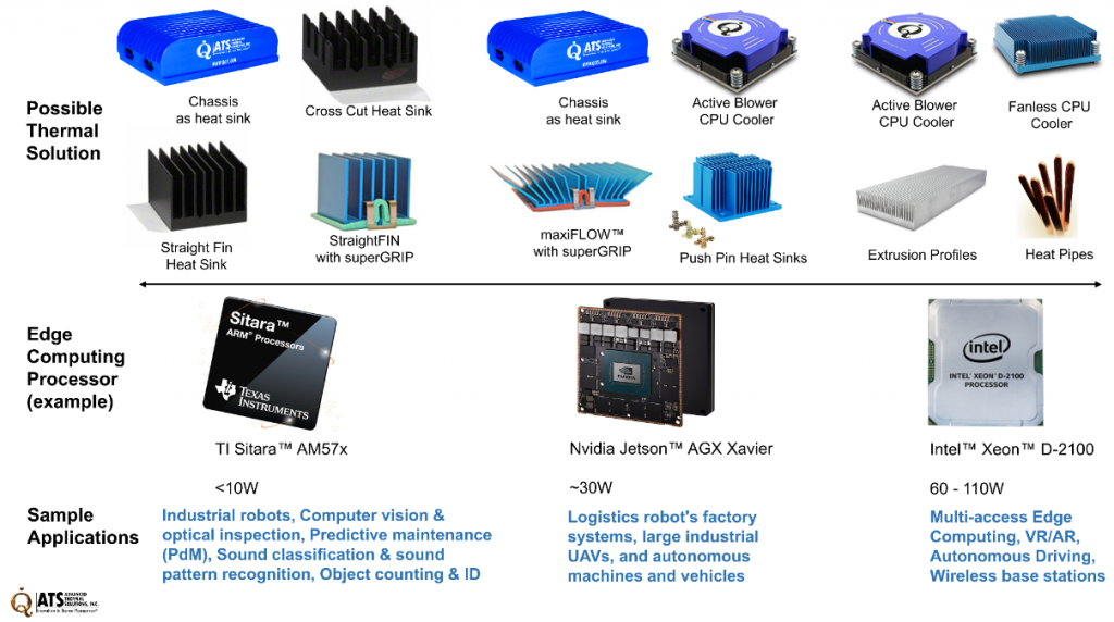
The following chart summarizes air cooling options for Edge Computing applications:
Figure 17: Edge Computing Air Cooling Options Summary Chart [click for larger version]
The Leading Edge
The edge computing marketplace is currently
experiencing a period of unprecedented growth. Edge market revenues are
predicted to expand to $6.72 billion by 2022 as it supports a global
IoT market expected to top $724 billion by 2023. The accumulation of IoT data,
and the need to process it at local collection points, will continue to drive
the deployment of edge computing. [28,29]
As more businesses and industries shift from enterprise to
edge computing, they are bringing the IT network closer to speed up data communications.
There are several benefits, including reduced data latency, increased real-time
analysis, and resulting efficiencies in operations and data management. Much critical
data also stays local, reducing security risks.
“Glover, G., Chen, Y., Luo, A., and Chu, H., “Thin Vapor Chamber Heat Sink and Embedded Heat Pipe Heat Sink Performance Evaluations”, 25th IEEE Symposium, San Jose, CA USA 2009.
The question arises, why pay more for a higher-efficient heat sink that is also smaller and lighter in weight, especially in cases whereby a simple, larger but heavier cast or extruded heat sink can also do the job? In most cases, the single piece part price is the main driver as to why engineers and purchasers stay with lesser effective solutions. This is generally because they believe that they are saving money for the company in the long-run.
But, is this really true?
It is very easy to compare the price of two single heat sinks, a highly efficient one versus a standard extruded type with the same thermal performance. But such a simplistic comparison does not take into account the flow performance, effect on neighboring and downstream components, weight, volume usage, etc.
(Advanced Thermal Solutions, Inc.)
What makes a heat sink an efficient heat sink you may wonder? Such a heat sink is optimized for both flow and heat transfer and, hence, makes much better use of the volume available for cooling and the existing cooling air. The geometry of the heat sink is optimized by using thin fins and a special design to lower the air resistance, resulting in the highest possible velocity in the fin field, while minimizing the effect of bypass flow. Because of this, it also has a lesser intrusive effect to the flow, which has a positive effect on the neighboring and downstream flows. This produces lower pressure drops over the board and through the system. The result of a comparison test, presented by Lasance C.J.M. and Eggink H.J., demonstrates this. [1]
The shape and the number of fins create the available surface area. The more surface area in contact with cooling air, the more energy can be dumped into the air and, therefore, the lower the heat sink temperature. Most important, the component temperature will also be lower. Of course, this is only valid if the temperature of cooling air going through the fin field is still lower than the fin temperature; otherwise, no net heat transfer from the heat sink to the air will occur. As has been shown in the literature, there exists an optimum correspondence between the number of fins and the overall cooling effect of these fins.
To arrive at a better comparison, let us look to other related effects which will result in a system price increase due to the chosen cooling solution:
Effect on the flow
Heat sink weight
Heat sink attachment
Mechanical adjustments required to handle the weight on both a board and system level, and to fulfill mechanical requirements for shock and vibration
Raw material usage to manufacture the cooling solution
Required fan performance
Product reliability
Transportation cost
End of life cost
Figure 1 shows a picture of a flow visualization test through a pin fin and the DUT. Compare the amount of flow entering the pin fin and the DUT, which in this case is a maxiFLOW™ heat sink. Most of the water “hitting” the pin fin is bypassing it because of the high air resistance of the fin field. Look at the flow that is left over downstream of the pin fin, which is lower than the upstream flow. Imagine what will happen if we put multiple pin fins in a row downstream of each other because we have to cool multiple devices in a row.
Fig. 1- Flow Test on Both a Pin-Fin (Left) and DUT (Right) in a Water Tunnel. The flow is from top to bottom. (Advanced Thermal Solutions, Inc.)
The first pin fin will have sufficient cooling but, the further we go downstream, the less effective the heat sink becomes. Limited air will be available for cooling, because most of the air is bypassing the heat sinks. What is the first reaction without knowing anything about the flow structure? We need a larger heat sink downstream to get the same cooling effect; or maybe we need to consider a more powerful fan system to drive more air through the system. However, if we would have started from a system level point of view instead of concentrating on a single heat sink, we would have studied the flow field and the interaction between the heat sink and the flow more closely, and we could have arrived at a better solution.
For example, in many cases the total number of heat sinks can be reduced, because other components are better cooled and probably do not require additional cooling.
Standard extruded heat sink profiles and cast heat sinks normally have a thick base and thick fins and are made of lesser thermally conductive aluminum alloys. The lower conductivity is a result of the additives that are included, to make the manufacturing of the product easier. The base and the fins tend to be thicker, because it is more difficult to manufacture thin and tall fins. Especially for natural convection, the optimum heat sink from a thermal point of view can easily be a factor of ten thinner than what is offered. The main design driver for these types of heat sink is the ease of manufacturing and not the overall thermal performance. The end result is a more voluminous and heavier heat sink that makes bad use of the available volume and has a negative effect on the flow.
To have a stable mechanical design, a stronger mechanical attachment to the component/board is required to handle the weight of standard heat sinks, as compared to high performance ones. An efficient light weight heat sink can still be attached by taping, glue, and other attachment methods, which use the component itself as an anchor.
Counting the weight of a standard heat sink and its attachment mechanism together, the overall product weight will be quite higher than for a design based on more efficient cooling solutions.
The same is valid for those LED designs that use the housing as a heat sink. The housing often is made by extrusion or casting processes, which limit the freedom of design. They are generally made of zinc aluminum (Zamac) with a thermal conductivity around 115 W/mK; whereas aluminum used for molding is between 100-150 W/mK; brass annealed is around 60 W/mK; aluminum alloy AL 6063 has a thermal conductivity of 201 W/mK and aluminum alloy AL 1050A reaches 229 W/mK.
Heat spreading is an important factor in most LED applications, and drives the thermal design of LED cooling. If analysis shows heat spreading is important, the consequence is that for lower conductivity materials, the only option is to either increase the base thickness or embed heat pipes or vapor chambers, adding to cost and weight.
Ephesus LED lighting solutions, with ATS thermal management design, was used in the recent Super Bowl at U.S. Bank Field in Minneapolis.
Forged heat sinks are made of high conductivity aluminum, but the manufacturing method itself is very limited in design freedom. So, in general, to get a better performance, a larger heat sink is required. For natural convection, the use of thermally conductive plastic could be of interest because of its lower weight and greater design freedom. Plastics enhanced with carbon fibers could also be used but require special attention because of their non-orthogonal conduction behavior. Other options are designs that are a combination of highly efficient heat sinks and heat pipes, to either improve heat spreading when the heat sink is much larger than the source, or to transport the heat from the source to a remote heat sink.
Apart from the attachment of the heat sink to one or more component, the overall weight of the board, including the cooling solutions, affects the overall mechanical design. Additional mechanical features are needed to make the product mechanically stable and these features will add cost and weight and further limit the design freedom.
As discussed before, a more voluminous heat sink solution requires more raw material. The initial manufacturing process of aluminum, however, is energy intensive, something we would like to decrease in a world where reduction of energy consumption is key. Fortunately, it can be recycled without the loss of its properties and the recycling process uses only a fraction of the energy in the initial manufacturing process. Finally, there are manufacturing techniques such as bonding, folding and skiving, that do not suffer from these sustainability issues.
Furthermore, a lesser efficient heat sink such as a pin fin or standard extruded type of heat sink, will lead to higher air resistance and lesser optimized flow over the components/ board and through the system. To overcome the higher air resistance and allow for more flow to compensate for the reduced airflow, a more powerful fan or more fans are required. A more powerful fan can mean either a larger fan type or permitting the current fan to run at a higher rotational speed. However, doubling the fan speed means increasing the input power to the fan by a factor of 8. As a result, more heat is dissipated in the system, the power supply has a higher current usage and more power is dissipated in the fan itself. This will lead to a higher fan temperature, thus reducing its lifetime. On top of this, a higher fan speed and more flow will result in higher noise levels.
Optimizing your thermal design by optimizing around the heat sink could in some cases avoid the use of a fan at all, making up for the extra costs of a more sophisticated heat sink. The use of more efficient cooling solutions will lead to a more optimized overall thermal design of the system, influencing directly the thermally and thermo-mechanically related reliability issues of the overall system. The transportation cost of the cooling solution to the manufacturer of the system also has a price. This price is based on shipped volume and weight. Efficient cooling solutions are lower in volume and lower in weight, so will yield a reduction in transportation costs. The weight factor is also applicable for the final product, as a product equipped with lesser weight cooling solutions will be cheaper to transport.
Apart from transport issues, a human effect is applicable: take, for instance, an LED-based streetlamp. Lifting a 30 kg lamp and installing it on a pole, versus lifting a 20 kg lamp, speaks for itself. Additionally, the pole needs to be designed in such a way that it can handle the weight of the lamp, potentially reducing the costs of a lesser weight lamp. Every product has a certain economic and technical lifetime and will be recycled afterwards. The cooling solution need to be recycled too. The heat sink, lamp enclosure – in most cases made of aluminium – can be recycled in a cost and energy effective way; but the lesser mass we recycle, the better.
In summary, the conclusion must be that it pays off to focus on the costs of the total system, and not only on the costs of the individual parts. In times long gone by, it was standard practice that project leaders got bonuses for buying parts as cheap as possible. Needless to say, such an attitude cannot survive in a world where end-users buy total systems, not a collection of parts. However, in the case of heat sinks, we still notice a sub-optimal purchasing policy, often based on lack of knowledge and outdated protocols.